Taipan95
Guest
Good morning.
I am trying to improve my knowledge about the drives electric motor + reducer (+ inverter, in this case).
I would like to try to dimensional a three-phase asynchronous motor, to be adjusted with inverter, trying to "copy" a case study that I saw at a training course but where it starts with the system already dimensioned and then focus on other aspects (in specific, on reaction forces on the bearings of the handle).
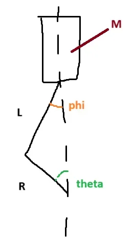
the system is a biella handle, with the biella that is connected to a fixed load of 20kg.
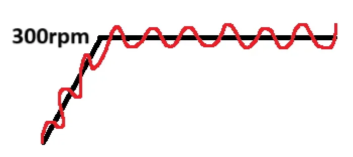
the crank must take to speed of regime (300rpm) after 2.5s, with a ramp to pleasure (I was considering a linear ramp from 0s to 2.5s for simplicity).
the crank is 175mm, the biella is 519mm.
We admit that these are all the starting data.
I tell you for completeness that in the case study is also inserted a motor between the crankshaft and the asynchronous motor, with a ratio about 3. But I guess that's coming later.
to be able to choose the three-phase asynchronous engine, I guess I have to calculate the torque profile needed to move this system with the desired timing and speeds. this should at least give me an order of magnitude on the size of the engine to use. After that, I think, they should follow the considerations on the inverter and the reducer.
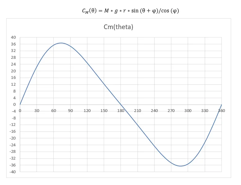
the problem is that in this case I have a sinusoidal load, because the mass from 20kg will move of alternating motion vertically following the bike of the biella-manovella.
I tried to calculate the necessary torque profile at 300 rpm, for a spin of crank, and I attach it together with a box showing the system. However I do not think it is correct, because it does not take into account the presence of the inverter and is also done only for the speed of regime without considering the transitory.
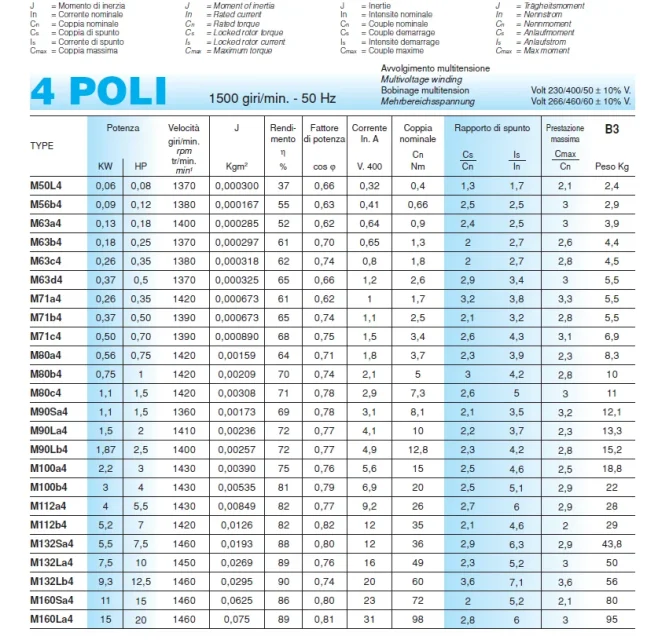
I don't really know where to start, I'd like someone, with a little patience, to be able to lead me to figure out how to size everything... I managed to find the engine catalogs and gearbox used in the case study, I also attach those.
the chosen engine is: m90sa4
the chosen reducer is: 411a one step 38nm
thanks to anyone who wants to contribute
I am trying to improve my knowledge about the drives electric motor + reducer (+ inverter, in this case).
I would like to try to dimensional a three-phase asynchronous motor, to be adjusted with inverter, trying to "copy" a case study that I saw at a training course but where it starts with the system already dimensioned and then focus on other aspects (in specific, on reaction forces on the bearings of the handle).
the system is a biella handle, with the biella that is connected to a fixed load of 20kg.
the crank must take to speed of regime (300rpm) after 2.5s, with a ramp to pleasure (I was considering a linear ramp from 0s to 2.5s for simplicity).
the crank is 175mm, the biella is 519mm.
We admit that these are all the starting data.
I tell you for completeness that in the case study is also inserted a motor between the crankshaft and the asynchronous motor, with a ratio about 3. But I guess that's coming later.
to be able to choose the three-phase asynchronous engine, I guess I have to calculate the torque profile needed to move this system with the desired timing and speeds. this should at least give me an order of magnitude on the size of the engine to use. After that, I think, they should follow the considerations on the inverter and the reducer.
the problem is that in this case I have a sinusoidal load, because the mass from 20kg will move of alternating motion vertically following the bike of the biella-manovella.
I tried to calculate the necessary torque profile at 300 rpm, for a spin of crank, and I attach it together with a box showing the system. However I do not think it is correct, because it does not take into account the presence of the inverter and is also done only for the speed of regime without considering the transitory.
I don't really know where to start, I'd like someone, with a little patience, to be able to lead me to figure out how to size everything... I managed to find the engine catalogs and gearbox used in the case study, I also attach those.
the chosen engine is: m90sa4
the chosen reducer is: 411a one step 38nm
thanks to anyone who wants to contribute