• This forum is the machine-generated translation of www.cad3d.it/forum1 - the Italian design community. Several terms are not translated correctly.

api e assemblaggio

Sbabba

Guest
Hello, everyone.

for the thesis I am working on an automatic assembly of a series of standard components in different configurations.
I wrote a c# program that allows the selection of these components and commands two cads, solid works and solid edge, for the assembly of the models of such components according to the chosen configuration.

regarding solid works I had no problem. I have inserted two floors between them orthogonal and one axis on the end of each piece, so that they can be coupled together through two commands of complanarity and one of coaxiality; this mating procedure is iterata for each pair of components until the final assembly is created, as the plans and axes always have the same name and sw selects plans and axes with a syntax of the type "name_piano@nome_parte@nome_assembly".

for precision the controls used are:

selectbyid2() for the selection of plans and axes with which to perform the coupling;
addmate3() for the addition of planar and axial coupling.

Now I'm trying to do the same thing with solid edge, but I have difficulties.

first I found the axialrelation3d() and planarrelation3d() commands to perform the matings, but I have a lot of doubts about how it can do. the sdk of st4 says (qui) that it is possible to use the command planarrelation3d() to make parallel two faces of two different parts: instead of two faces, would it be possible to use two floors created by me, named in a very precise way, so as to apply the same iterative command for the various components?

As far as coaxiality is concerned, it seems to me that it is not possible, because the axialrelation3d() command makes two axes of two cylindrical parts, but in my case I have not only cylindrical parts; Moreover if it does not allow, unlike sw, to insert axes to pleasure. I could easily solve the problem using a third floor and a third conspiracy, but I wanted to make sure of this.

Unfortunately online there are very little information regarding the use of solid edge bees with assembly, and the sdk of if is extremely scarce if compared to that of sw, then brancolo a little in the dark.

I thank in advance anyone who can give me even the smallest help!! and on the extremit
axes in solid edge can be created, the command is hidden and to pull out. I recommend that you use the coordinate systems that at the same time contain both axes and plans.

then you can enter the relationship that makes two coordinate systems coincide, and with one relationship positions the part.

You can still follow the path you take, instead of the faces you will have to give them plans.

search for the commands "addplanar" and "addaxial", the documentation for solid edge programming is very well written I doubt that you are looking in the wrong place.

Hi.
 
the advice of using the coordinate system seems very good to me. Alternatively, for the axis, I would propose a sketch with a line.
to select an item, the simplest method (according to my capabilities) is to use the index, although for some object also functions the name:
selection by name: family("name")
selection of the first: family(0)
selection of the last: family(subjects.count()- 1 )

the reference plans I think are always the first, you can determine whether the first or last sketch contains your axes.
for programming with solid edge I suggest the following links, if you already do not know them:
sespy: http://solidedgespy.codeplex.com/
di http://www.jasonnewell.net/
 
Thanks for the answers!

Sorry I'm late, I've had the last exam before graduation and he's taken me a lot! Now I can fully focus on thesis:)

The idea of the coordinate system seems great! I am trying to use it, but I encounter difficulties.

I took as a base This is what guide, then rewriting the commands for c#.

Now, I have opened two assembly files that I have to match the coordinate systems, they are "seassy1" and "seassy2", and I have acquired the coordinate system with these commands:
Code:
seassy1cos = seassy1.coordinatesystems.item(2);
seassy2cos = seassy2.coordinatesystems.item(2);
item(2) because the first is the default one, the second is what I created.

the guide then says to use the command "getorientation()" to get the "details of the coordinate system".
Code:
seassy1cos.getorientation(axo, ayo, azo, axr, ayr, azr);
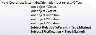
But here I find a mistake. visual study points out that two parameters are missing at the command, which would be "relativetoparent" and "zfirstrotation" ( http://dl2.plm.automation.siemens.c...edgepart~coordinatesystem~getorientation.html )
I do not understand exactly what parameters it is, in the sense that visual study in the help of compilation tells me this
err.webpAnd I don't know what "type.missing" is. Moreover according to the command page get orientation on the siemens site, each parameter should be optional, and for this the guide, I think, you do not bring them all, but it seems that they are not at all optional in reality :d

I tried to fly over and go further, to conclude something, so I still followed the guide that at this point wants to extract the plans that define the coordinate system. it does so with the command "coordinatesystem.plane()" that wants to parameter the constant indicating the plan you want to extract, that I found here.
Code:
assyxyplane = seassy1cos.plane(secoordsysxyplane);
the problem is that visual study is not yet happy, and tells me "indexed property solideedgepart.coordinatesystem.plane has non-optional argument that must be provided". I don't understand. the parameter to provide is only one, the constant that indicates the plan, and also in the auto compilation vs me asks only one... what do you mean by "non-optional parameter" that I wouldn't be giving him?

every time I take a step forward I take two back... It is absurd because I am sure it is a very simple thing, but at the moment it seems impossible! !

I thank you in advance for any help you can give me. thanks also for the advice of solid edge spy, really useful!
 
in the solid edge guide the parameters of getorientation indicate them all as "variant" so I wouldn't worry too much and insert two variables of this type.

I just tried in vb6 and the following code works, unfortunately I don't program in c so I can't help you if I don't advise you to ask on the forum where you found the code you're talking about.
Code:
    dim objapp as solidedgeframework.application
    dim objasm as solidedgeassembly.assemblydocument
    
    dim piano as solidedgegeometry.face
    
    set objapp = getobject(, "solidedge.application")
    set objasm = objapp.activedocument
    
    set piano = objasm.coordinatesystems(2).plane(secoordsysxyplane)
 
Thanks for the quick answer, now I try! the fact that it is in vb is not a problem, so much c# is very similar!

However I discovered the reason for the first mistake, the one on the getorientation(). wants some parameters like "object" and they have to be set out, so the correct syntax is "getorientation(out axo, out ayo, out azo, out axr, out ayr, out azr);" with axo...azr declared object, and not double as that guide did (which, therefore, I wonder how it could work :d).

Thanks again:)
 
So I did it! In short, almost :d

then after a little peripecies I wrote this code, which can perfectly align the coordinate systems of two pieces, but only those! I'll explain.

I start by inserting a variable number of components (minimum 5, max 8) into a assembly I create at the moment. These components are all assembly apart from one .par. the assembly function is unique and is called several times in a cycle so as to combine all the necessary components. I know the order of insertion of the components of the assembly, which is the same in which they will be ordered, so to the function step a variable "c" which indicates the position in the order, so that the code merges from time to time the c-th component with the c-th + 1.
Code:
//mi connect to the assembly created for the display of the assembly
seassy = application.activedocument;

//creo the ocurrence relative to the two components
seocc1 = seassy.occurrences.item(c);
seocc2 = seassy.occurrences.item(c+1);

//I take the coordinate system from me created for each component. only for the first assembly will be number (2)
if (c == 1)
(')
seocc1cos = seocc1.occurrencedocument.coordinatesystems.item(2);
?
♪
(')
seocc1cos = seocc1.occurrencedocument.coordinatesystems.item(3);
?

seocc2cos = seocc2.occurrencedocument.coordinatesystems.item(2);


//I buy details of the coordinate system from me created
seocc1cos.getorientation(out a1xo, out a1yo, out a1zo, out a1xr, out a1yr, out a1zr);
seocc2cos.getorientation(out a2xo, out a2yo, out a2zo, out a2xr, out a2yr, out a2zr);


//I buy the plans that make up the coordinate system I created
occ1xyplane = seocc1cos.plane[SolidEdgePart.CoordinateSystemFeatureConstants.seCoordSysXYPlane];
occ1yzplane = seocc1cos.plane[SolidEdgePart.CoordinateSystemFeatureConstants.seCoordSysYZPlane];
occ1zxplane = seocc1cos.plane[SolidEdgePart.CoordinateSystemFeatureConstants.seCoordSysZXPlane];

occ2xyplane = seocc2cos.plane[SolidEdgePart.CoordinateSystemFeatureConstants.seCoordSysXYPlane];
occ2yzplane = seocc2cos.plane[SolidEdgePart.CoordinateSystemFeatureConstants.seCoordSysYZPlane];
occ2zxplane = seocc2cos.plane[SolidEdgePart.CoordinateSystemFeatureConstants.seCoordSysZXPlane];


            //cancello la relazione ground dei due componenti
            seocc1.relations3d.item(1).delete();
            seocc2.relations3d.item(1).delete();

            //acuisisco le relazioni del pezzo
            serels3d = seassy.relations3d;


            //creo un reference fra il pezzo e il piano ed aggiunge la relazione planare
            serefocc1 = seassy.createreference(seocc1, occ1xyplane);
            serefocc2 = seassy.createreference(seocc2, occ2xyplane);
            serels3d.addplanar(serefocc1, serefocc2, false, constrainingpoint, constrainingpoint);

            serefocc1 = seassy.createreference(seocc1, occ1yzplane);
            serefocc2 = seassy.createreference(seocc2, occ2yzplane);
            serels3d.addplanar(serefocc1, serefocc2, false, constrainingpoint, constrainingpoint);

            serefocc1 = seassy.createreference(seocc1, occ1zxplane);
            serefocc2 = seassy.createreference(seocc2, occ2zxplane);
            serels3d.addplanar(serefocc1, serefocc2, false, constrainingpoint, constrainingpoint);
Note: when I acquire the coordinate system I put a if {} because all the components assemble vertically one above the other, so from time to time I take the coordinate system of the one below and join it to that of the piece above. the first component, however, has only one system of coordinates created by me, because being always the first will never have the need to be connected with 2 components, but only with one who will stand on it. That's why I'm doing it.


now the code works because the first two components are assembled perfectly, the problem arises in the second cycle. it still does the initial part without problems, but it gives error when it reaches the time to create the reference and then make the coupling. in particular it goes wrong on:
Code:
serefocc1 = seassy.createreference(seocc1, occ1xyplane);
I thought maybe it was because "serefocc1" was not initialized to "null", but also in that way it makes a mistake. I thought maybe it should be able to keep the old references, so I tried to make the second assembly with a different variable, like "serefocc3", but it also makes a mistake like that.

clearly to the second assembly "seocc1" is a different component from before, in particular it is the second that I assembled previously (what before was "seocc2"), and occ1xyplane is the xy plan taken from its coordinate system.


I don't understand what the problem is, and it's definitely solid edge. I obviously miss something about how the occurrences, the reference and the creatireference(), but I don't understand what it might be.

Does anyone have an idea what the problem might be? I'd practically finish this! !

I thank you again for the attention, you are very kind:
 
What kind of mistake is coming out of you?

from a quick read of your code the first component is not bound to anything and therefore able to move.
It would be good to leave him the land relationship. this is true in all situations, the main component must be bound to the ground.

Hi.
 
Thanks for the answer.

then I realized a mistake, in the sense that since all that code is called several times in fact is as if it was in a cycle, so at every time I tried to eliminate the relations of the two pieces that was assembling at that time, but clearly one of the two had already been assembled before and therefore the ground report had already been removed previously.

I modified the code so as to remove the constraints to all pieces except the first time the function is called.
I also initialized to "null" all variables so as to eliminate possible residual information.

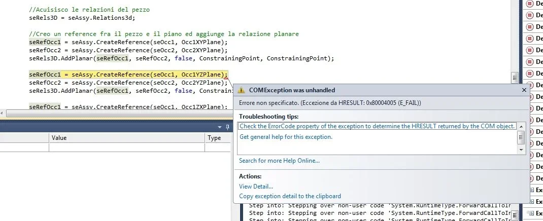
now, after initializing to null, the program still assembles the first and second piece, then when the function repeats itself for the assembly of the second with the third one it blocks on the second "createreference", that with the yz plan. The error is this
err.webpIt's so generic that I can't figure out where you're wrong, so I said that I'm sure I'm missing something in the method of the creationreference(), the problem is that I don't understand what... besides the first creationreference() with the xy plan does.

Now maybe I try to blow that component and move on to the next, maybe it's a model problem.

Thank you and hello!
 
edit: I tried to hand-assemble the two pieces using the two coordinate systems and I have no problem with it, so the pieces don't think they have any problems. increasingly incomprehensible :d


this is the current code, compared to before I only modified the elimination of the earth bond on the components.

Code:
//mi connect to the assembly created for displaying the prosthesis
seassy = application.activedocument;

//creo the ocurrence relative to the two components. c initially worth 1 and is increased to each call of this function
seocc1 = seassy.occurrences.item(c);
seocc2 = seassy.occurrences.item(c+1);

//I take the coordinate system from me created for each component. only for the first assembly will be number (2)
if (c == 1)
(')
//cancel the ground relationship of all components except the first, which must remain fixed
int countocc = seassy.occurrences.count;
int a = 2;

while (a <= countocc)
(')
seassy.occurrences.item(a).relations3d.item(1). delete();
a++;
?
seocc1cos = seocc1.occurrencedocument.coordinatesystems.item(2);
?
♪
(')
seocc1cos = seocc1.occurrencedocument.coordinatesystems.item(3);
?

seocc2cos = seocc2.occurrencedocument.coordinatesystems.item(2);

//I buy details of the coordinate system from me created
seocc1cos.getorientation(out a1xo, out a1yo, out a1zo, out a1xr, out a1yr, out a1zr);
seocc2cos.getorientation(out a2xo, out a2yo, out a2zo, out a2xr, out a2yr, out a2zr);

//I buy the plans that make up the coordinate system I created
occ1xyplane = seocc1cos.plane[SolidEdgePart.CoordinateSystemFeatureConstants.seCoordSysXYPlane];
occ1yzplane = seocc1cos.plane[SolidEdgePart.CoordinateSystemFeatureConstants.seCoordSysYZPlane];
occ1zxplane = seocc1cos.plane[SolidEdgePart.CoordinateSystemFeatureConstants.seCoordSysZXPlane];

occ2xyplane = seocc2cos.plane[SolidEdgePart.CoordinateSystemFeatureConstants.seCoordSysXYPlane];
occ2yzplane = seocc2cos.plane[SolidEdgePart.CoordinateSystemFeatureConstants.seCoordSysYZPlane];
occ2zxplane = seocc2cos.plane[SolidEdgePart.CoordinateSystemFeatureConstants.seCoordSysZXPlane];


            //acuisisco le relazioni del pezzo
            serels3d = seassy.relations3d;

            //creo un reference fra il pezzo e il piano ed aggiunge la relazione planare
            serefocc1 = seassy.createreference(seocc1, occ1xyplane);
            serefocc2 = seassy.createreference(seocc2, occ2xyplane);
            serels3d.addplanar(serefocc1, serefocc2, false, constrainingpoint, constrainingpoint);

            serefocc1 = seassy.createreference(seocc1, occ1yzplane);
            serefocc2 = seassy.createreference(seocc2, occ2yzplane);
            serels3d.addplanar(serefocc1, serefocc2, false, constrainingpoint, constrainingpoint);

            serefocc1 = seassy.createreference(seocc1, occ1zxplane);
            serefocc2 = seassy.createreference(seocc2, occ2zxplane);
            serels3d.addplanar(serefocc1, serefocc2, false, constrainingpoint, constrainingpoint);
 
I also tried changing the pieces, always nailed on the creation of reference between the piece and its yz plan, regardless of the coordinate system or the piece I take.

when it does it for the first of the pieces it works, with any other crash, yet with the xy plan it does not give problems and the coordinate systems have been built in the same way. I don't understand. .
 
in vb6 this is how I would do it, and it works.

Hi.
Code:
private sub assembla()
    
    dim objapp as solidedgeframework.application
    dim objasm as solidedgeassembly.assemblydocument
    
    dim objocc1 as solidedgeassembly.occurrence
    dim objocc2 as solidedgeassembly.occurrence
    
    dim objocc1cs as solidedgepart.coordinatesystem
    dim objocc2cs as solidedgepart.coordinatesystem
    
    dim objocc1xyplane as solidedgegeometry.face
    dim objocc1yzplane as solidedgegeometry.face
    dim objocc1zxplane as solidedgegeometry.face
    dim objocc2xyplane as solidedgegeometry.face
    dim objocc2yzplane as solidedgegeometry.face
    dim objocc2zxplane as solidedgegeometry.face
    
    dim xyzpoints1(1 to 6) as double
    dim xyzpoints2(1 to 6) as double
    
    dim objocc1ref as solidedgeframework.reference
    dim objocc2ref as solidedgeframework.reference
    
    set objapp = getobject(, "solidedge.application")
    set objasm = objapp.activedocument
    
    for each occurrence in objasm.occurrences
        
        if occurrence.index <> objasm.occurrences.count then
        
            set objocc1 = occurrence
            set objocc2 = objasm.occurrences.item(objocc1.index + 1)
            
            for i = objocc2.relations3d.count to 1 step -1
                objocc2.relations3d(i).delete
            next i
            
            set objocc1cs = objocc1.occurrencedocument.coordinatesystems(2)
            set objocc2cs = objocc2.occurrencedocument.coordinatesystems(3)
            
            call objocc1cs.getorientation(xyzpoints1(1), xyzpoints1(2), xyzpoints1(3), xyzpoints1(4), xyzpoints1(5), xyzpoints1(6))
            call objocc2cs.getorientation(xyzpoints2(1), xyzpoints2(2), xyzpoints2(3), xyzpoints2(4), xyzpoints2(5), xyzpoints2(6))
            
            set objocc1xyplane = objocc1cs.plane(secoordsysxyplane)
            set objocc1yzplane = objocc1cs.plane(secoordsysyzplane)
            set objocc1zxplane = objocc1cs.plane(secoordsyszxplane)
            
            set objocc2xyplane = objocc2cs.plane(secoordsysxyplane)
            set objocc2yzplane = objocc2cs.plane(secoordsysyzplane)
            set objocc2zxplane = objocc2cs.plane(secoordsyszxplane)
            
            set objocc1ref = objasm.createreference(objocc1, objocc1xyplane)
            set objocc2ref = objasm.createreference(objocc2, objocc2xyplane)
            
            call objasm.relations3d.addplanar(objocc1ref, objocc2ref, false, xyzpoints1, xyzpoints2)
            
            set objocc1ref = objasm.createreference(objocc1, objocc1yzplane)
            set objocc2ref = objasm.createreference(objocc2, objocc2yzplane)
            
            call objasm.relations3d.addplanar(objocc1ref, objocc2ref, false, xyzpoints1, xyzpoints2)
            
            set objocc1ref = objasm.createreference(objocc1, objocc1zxplane)
            set objocc2ref = objasm.createreference(objocc2, objocc2zxplane)
            
            call objasm.relations3d.addplanar(objocc1ref, objocc2ref, false, xyzpoints1, xyzpoints2)
            
        end if
        
    next occurrence
    
end sub
 
Bye!

your code is practically like mine, in fact also my works with the first assembly.

on the second assembly performs the addplanar on the first couple of floors (any it is: xy, yz, zx), then when I create again reference to call for the second time the addplanar always crashes on the creation of reference. and crash regardless of which floor you use! !

i.e. if I first do the xy and then the yz:
Code:
 set objocc1ref = objasm.createreference(objocc1, objocc1xyplane)
set objocc2ref = objasm.createreference(objocc2, objocc2xyplane)

call objasm.relations3d.addplanar(objocc1ref, objocc2ref, false, xyzpoints1, xyzpoints2)

set objocc1ref = objasm.createreference(objocc1, objocc1yzplane)
set objocc2ref = objasm.createreference(objocc2, objocc2yzplane)

call objasm.relations3d.addplanar(objocc1ref, objocc2ref, false, xyzpoints1, xyzpoints2)
fa l'xy ma crasha sull'yz, cioè su "set objocc1ref = objasm.createreference(objocc1, objocc1yzplane)"

mentre se scambio l'ordine facendo prima l'yz e poi l'xy:
Code:
 set objocc1ref = objasm.createreference(objocc1, objocc1yzplane)
set objocc2ref = objasm.createreference(objocc2, objocc2yzplane)

call objasm.relations3d.addplanar(objocc1ref, objocc2ref, false, xyzpoints1, xyzpoints2)

set objocc1ref = objasm.createreference(objocc1, objocc1xyplane)
set objocc2ref = objasm.createreference(objocc2, objocc2xyplane)

call objasm.relations3d.addplanar(objocc1ref, objocc2ref, false, xyzpoints1, xyzpoints2)
makes the yz but crashes on the xy, "set objocc1ref = objasm.createreference(objocc1, objocc1xyplane)"

practically always crashes on the second reference, while the first always manages to create it, regardless of which plans I use! I tried with zx, same speech.

I don't understand what it's like. Why ever on the second?
 
in your code write:
Code:
serels3d.addplanar(serefocc1, serefocc2, false, constrainingpoint, constrainingpoint)
in practice use the same point (constrainingpoint) for orientation and I don't think it can work.
the two points must be related to the two faces that give it as a parameter.

in my code in fact use xyzpoints1 and xyzpoints2

verification
 
ok now I fix it, but he does not crash on addplanar but on createreference, so I don't think that's why.
 
ok now I fix it, but he does not crash on addplanar but on createreference, so I don't think that's why.
I believe that we are creating seemingly valid relationships that create problems to the next ones.
have you verified the reports created in what state are they?

Hi.
 
Thank you, I did as you told me but unfortunately I always find the same mistake.

Where do I see her? by spy I can't find the voice "reference".

I'm sorry to take advantage of it, but can I try to pass the 3 components I'm assembling? Maybe you see the mistake where I've been banging my head for three days. .

the problem is when creating the second reference between the third coordinate system of piece 2 (sc_join_upper) and piece 2.

Thank you very much, you are very kind.
 

Attachments

Thank you, I did as you told me but unfortunately I always find the same mistake.

Where do I see her? by spy I can't find the voice "reference".

I'm sorry to take advantage of it, but can I try to pass the 3 components I'm assembling? Maybe you see the mistake where I've been banging my head for three days. .

the problem is when creating the second reference between the third coordinate system of piece 2 (sc_join_upper) and piece 2.

Thank you very much, you are very kind.
I intend to look at the relationships between the pieces inside the cad not in programming.
However the reports find them in occurrenceencedocument.relations3d

tomorrow I look at it now I have no vb

Hi.

p.s.: what version of solid edge you use and with which mp? maybe it is a kiss that was then solved and you just need an update.
 
the version is the st5, I don't know why my is the academic version, but I know it is the 105.00.00.102

I thought about it myself, I'm downloading st6 and after I try it!
 

Forum statistics

Threads
44,997
Messages
339,767
Members
4
Latest member
ibt

Members online

No members online now.

Back
Top