• This forum is the machine-generated translation of www.cad3d.it/forum1 - the Italian design community. Several terms are not translated correctly.

[ application moment fletnte ansys classic]

  • Thread starter Thread starter volaff
  • Start date Start date

volaff

Guest
Hi guys.
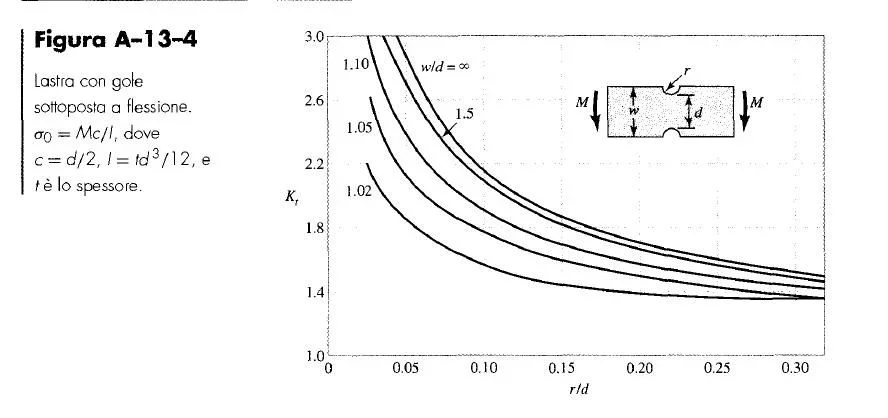
i have to found stress concentration factor for a plate with hole subjected to bending moment. i have modelled 1/4 of audience and applied symmetry and antisymmetry constraints.
how can model bending moment?
i think a couple of forces on top side but i don't have good results.
Thanks to all for helping me.

Bye, guys.
I should find the factor of concentration of tensions for this plate with hole subject to bending moment at the ends.
I modeled 1/4 of plate (plane 82) and applied symmetry and hemisymmetry constraints on the sides.
How can I shape the moment?
I had thought of a couple of strength on the upper side of module equal to the moment divided the distance, which in fact on the 1/4 of plate would mean having a force in the upper node to the extreme right of the plate.

thanks to all for the advice.
 

Attachments

  • Immagine.webp
    Immagine.webp
    33.6 KB · Views: 14
  • esercizio1.webp
    esercizio1.webp
    42.4 KB · Views: 11
I could model the pure bending load as variable pressure linearly between +p and –p values
(from command line: sfl,line,pres,p,-p). Right? a practical example?
 
ciao volaff,
I had thought of a couple of strength on the upper side of module equal to the moment divided the distance, which in fact on the 1/4 of plate would mean having a force in the upper node to the extreme right of the plate.
could be a good idea; Then, since you think the theoretical result knows, if it comes too different, you can always refine the model! :redface:
 
You may also calculate the "failure" of tensions and apply the tensions themselves as pressures on the top line of your image (from the max to zero tens at the neutral axis). .
 
Something like that?
where by p I mean the value of the applied moment divided the area where it is applied (w*t) with t thickness, in this way I get a pressure per unit length.

or do you mean a variable pressure between -p,p with zero value at the center of the plate?

I shaped half the plate here.
 

Attachments

  • Immagine3.webp
    Immagine3.webp
    33.3 KB · Views: 13
Hi.
I meant zero value in half of the plate.
I referred back to the case of pure bending with tensions having butterfly distribution (so null in the center).

Bye!
 
Bye!
I got confused and plotted an image for another.

I think you're referring to the one in the annex.
Right? at the ends the values are -p and +p.

thanks for the answers and availability.

Good evening!
 

Attachments

  • esercizio1.webp
    esercizio1.webp
    49.2 KB · Views: 12
Hi.
Yes but if you only model a quarter (good choice) you only go from max to zero, according to me.

Bye!
 
Bye.
the diagram I have is the following where the maximum load at the ends (considering half plate) that I applied the place equal to mf/(d*h)= 16*e007 n/mm.

the fact is that I do not find a value concorded with the kt obtained from the diagrams.
There's something wrong.

Thank you for your concern.
 

Attachments

  • schema.webp
    schema.webp
    9.2 KB · Views: 38
  • image.webp
    image.webp
    51.3 KB · Views: 8
Hi.
according to your image the tensions are compression. . Are you sure you applied the load in the right direction?
flat voltage models?

Bye!
 
Bye.
model with plane82 and the part you see refers to the 1/4 of the slab on the top right and, if you consider the other antisymmetric, you should do a pair that in the verse is concord with applied mf.
 
Hello volaff,
ok that the direction of tensions is agreed, but I would try to apply a traction load in the simulation, because I am not sure that the simulator interprets in the same way compression tensions.

Bye!
 
Hello volaff,
ok that the direction of tensions is agreed, but I would try to apply a traction load in the simulation, because I am not sure that the simulator interprets in the same way compression tensions.

Bye!
Bye.
I solved the problem by applying a triangular load that simulates the bending moment on 1/4 plate.
Now I try to solve the same problem differently.
 

Forum statistics

Threads
44,997
Messages
339,767
Members
4
Latest member
ibt

Members online

No members online now.
Back
Top