Mario887
Guest
hello to all I am new to the forum my name is Mario and currently aviation study at the university of roma.
I have from 1 started to use solidworks and are struggling with a design of a front trolley of a aircraft.
the problem that has arisen is in the cinematics of the final assembly.
I would need to insert the "assembly" file of solidworks so that you can give me a help, I hope it is allowed. practically what happens is that a simple manovellism that on paper (making a bit of calculations and graphic simulations 2d) seems to work wonder, in reality when I fix a bearing around which all the tavellism should rotate, solidworks instead I notify me that the selected element is completely defined therefore has no freedom of movement.
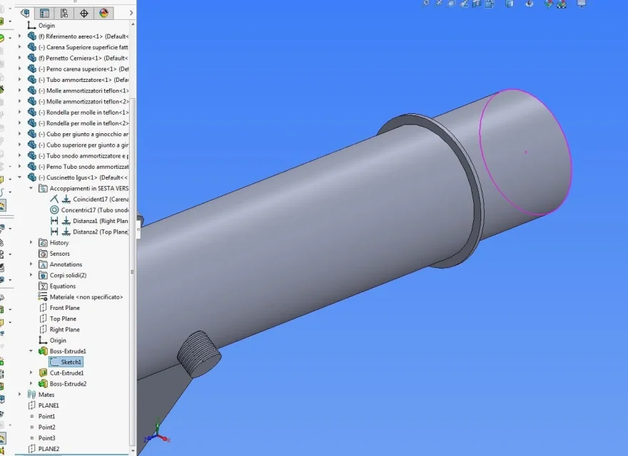
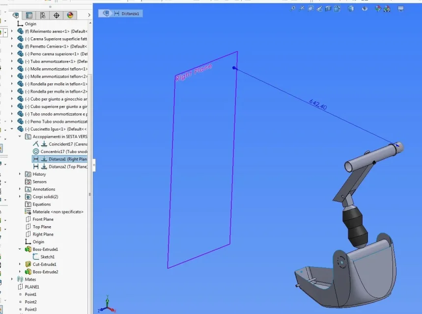
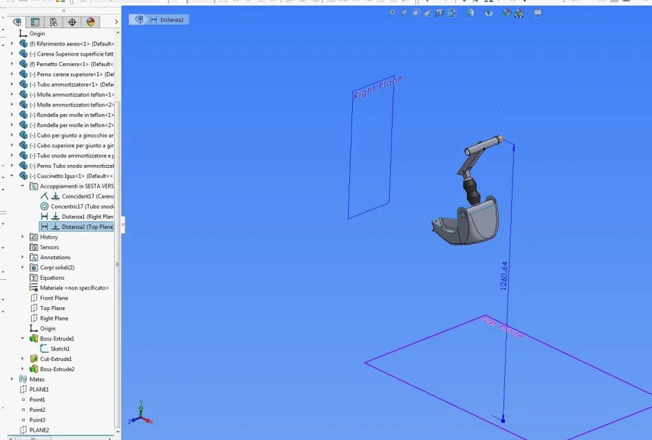
opening the file "sesta version....sldasm" by binding the "igus cushion" as "fix" (fixed part to a large frame, as well as "hinge pin"), putting the concentricity relationship with the element "tubo tube snodo shock absorber and piston", then the "superior shoe" should at least describe a fixed angle with the "top edge"View attachment Manovellismo Carrello Anteriore.rar
I have from 1 started to use solidworks and are struggling with a design of a front trolley of a aircraft.
the problem that has arisen is in the cinematics of the final assembly.
I would need to insert the "assembly" file of solidworks so that you can give me a help, I hope it is allowed. practically what happens is that a simple manovellism that on paper (making a bit of calculations and graphic simulations 2d) seems to work wonder, in reality when I fix a bearing around which all the tavellism should rotate, solidworks instead I notify me that the selected element is completely defined therefore has no freedom of movement.
opening the file "sesta version....sldasm" by binding the "igus cushion" as "fix" (fixed part to a large frame, as well as "hinge pin"), putting the concentricity relationship with the element "tubo tube snodo shock absorber and piston", then the "superior shoe" should at least describe a fixed angle with the "top edge"View attachment Manovellismo Carrello Anteriore.rar
")