• This forum is the machine-generated translation of www.cad3d.it/forum1 - the Italian design community. Several terms are not translated correctly.

asymmetric object rotation

  • Thread starter Thread starter Mito125
  • Start date Start date

Mito125

Guest
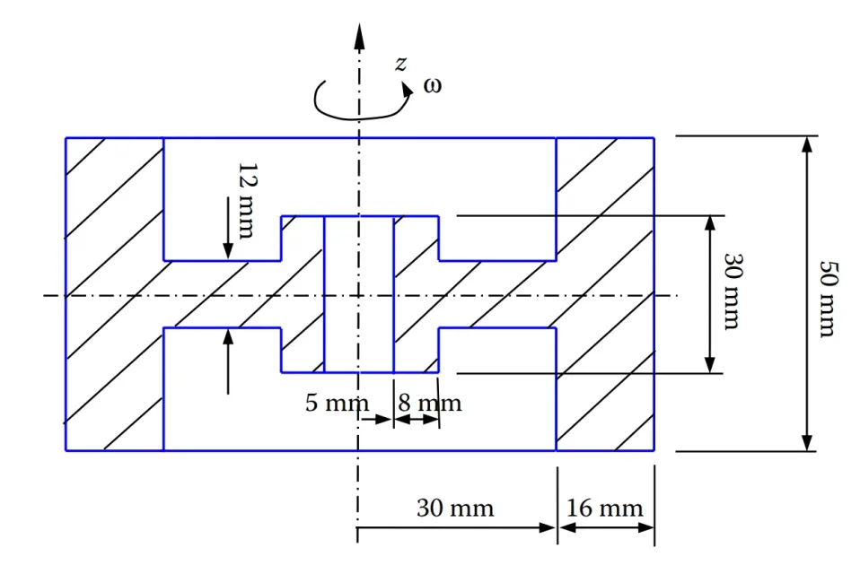
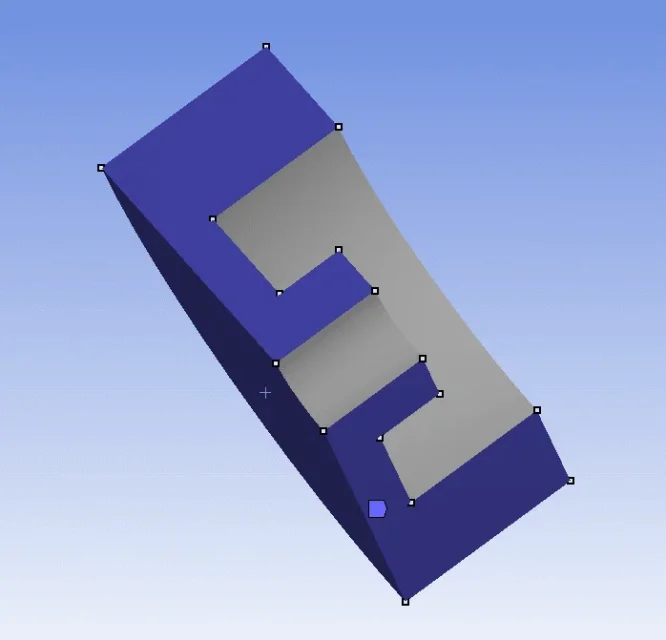
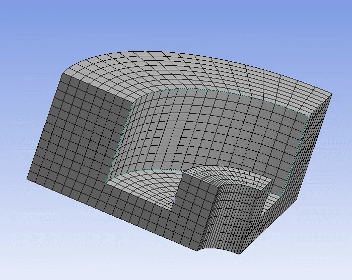
good morning, i'm trying to figure out whether the setting of the problem is correct or not. i have an object that rotates to 100rpm, the section of the object is as follows:1594628992534.webpi shaped the complete object as a rotation solid, getting the complete 3d object. i then applied the 3-storey long symmetry tool so that only one eye of the object. within model i entered 3 frictionless support to indicate the faces of the symmetry:1594629154215.webpi have inserted a standard earth gravity and then inserted into components the rad/s rotation (about 10.47). the mesh seems very tidy to me:1594629260535.webpdid i fix it properly? are in doubt regarding frictionless support and if the symmetric division is correct. thank you.
 
if you do not specify what you are trying to calculate and what the boundary conditions are, you cannot give you advice.

the symmetries can be exploited if the piece is asymmetrical, but as long as these symmetries do not go to cripple the load and bond conditions.
 
i have an object that rotates to 100rpm, i must find deformation and stress according to von mises.
 
ah without any loads or friction in the hub? then, neglecting gravity, the only load will be the centrifugal force ... your modeling at the end is fine, i think the problem could be reduced even to a 2d. the frictionless surfaces to shape the symmetry are commonly used because basically you tell the surface that can not deform along your normal... i am not sure, but it seems to me that there are specific constraints for symmetries. you can try both but should not give differences.

to answer your question.

i've never done static analysis by giving a speed as a load.. when did you get the results backed up? i am curious to see how the equivalent load is calculated accordingly the effort. take into account that you will have to radially bind the hub, in the posted images you do not see the bond, but i imagine that you know.
 
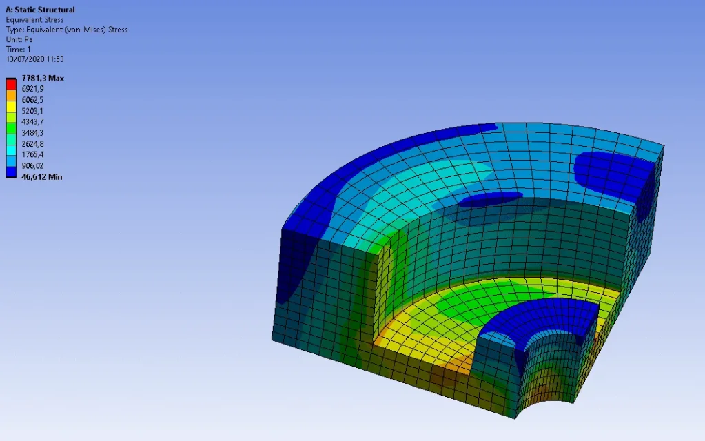
i've inserted gravity. i didn't give fixed constraints to support, so i made a serious mistake. i repeat by binding the internal surface as fixed. i repeated the analysis and placed here the result of von mises:1594634048169.webpi have questions about modeling. could i only model the clove without using the symmetry tool? i would have saved time in the drawing. or do i have to insert the symmetry tool to make him understand what i'm working on?

in case on the upper surface (in the section view is the highest part) there had been a load of 1000n, on the clove should i have inserted a load of only 250n? and if the load was also on the lower face, how could i do to indicate it? perhaps eliminating a symmetry plan?

can be modeled in 2d, the exercise in fact proposes the comparison between the results between 2d and 3d.
 
could i only model the clove without using the symmetry tool? i would have saved time in the drawing. or do i have to insert the symmetry tool to make him understand what i'm working on?
yes. the modeling strategy you use in the cad part is influential from the perspective of the fem. he needs geometry. with what steps it is realized does not matter.
in case on the upper surface (in the section view is the highest part) there had been a load of 1000n, on the clove should i have inserted a load of only 250n? and if the load was also on the lower face, how could i do to indicate it? perhaps eliminating a symmetry plan?
you better think in terms of pressure. you calculate by hand force divided area, then you can cut your surface as you want, the load in terms of pressure must always be that. applying a concentrated load instead actually arises doubt.
 
If I had the pressure I wouldn't have any problems, a pressure on a surface always remains that... My problem is concentrated loads... in an exercise done by dividing by symmetry divides the load but I do not feel safe. . .
 
Okay, but in the big case you can count on your hand... Am I wrong? 1000 n. 100 mm^2 —> 10 mpa ... apply the 10 mpa and you are suitable for all symmetries you want to apply
 
you are perfectly right, it is an adoptable solution. . I thought there was another system to adopt... still with the symmetries, I don't do it well. Thanks for the help. Too bad that in the book I'm using there are no results so I can compare myself directly. . .
 
It is curious to see that the result you plotted does not have a uniform pattern in the tangential direction, as it should be for a asymmetrical structure.
In fact, these structures can be studied with a flat mesh and asymmetric elements, considering that it is loaded that constraints are. Intrigued, I remodeled your structure and my result is asymmetric.
regarding the bond on the inner cylindrical face, this may also not be there. a disc that rotates with a certain angle speed is in balance for the masses, so it has no bond. if it is calettated on a board, this is often a constraint to rotation (language, grooved profile, etc.) and not to radial translation.
so, I would be bound only on the three floors where you imposed the symmetry, it would be the situation of a disc in rotation, in balance, that does not exchange other forces with the outside.
 
Can I see how you shaped and applied constraints? I'd like to compare.

I imposed on the three symmetry plans of the frictionless constraints, so the fixed bond within the central hole does not serve?
 
for the constraints I have put that the superifices remain flat, (frictionless) on the three faces of symmetry. for the central hole, I did not put any constraint, just as if the disk floated in balance with only the rotation force that acts uniformly.
 

Forum statistics

Threads
44,997
Messages
339,767
Members
4
Latest member
ibt

Members online

No members online now.
Back
Top