fabrypiro
Guest
Good morning to all,
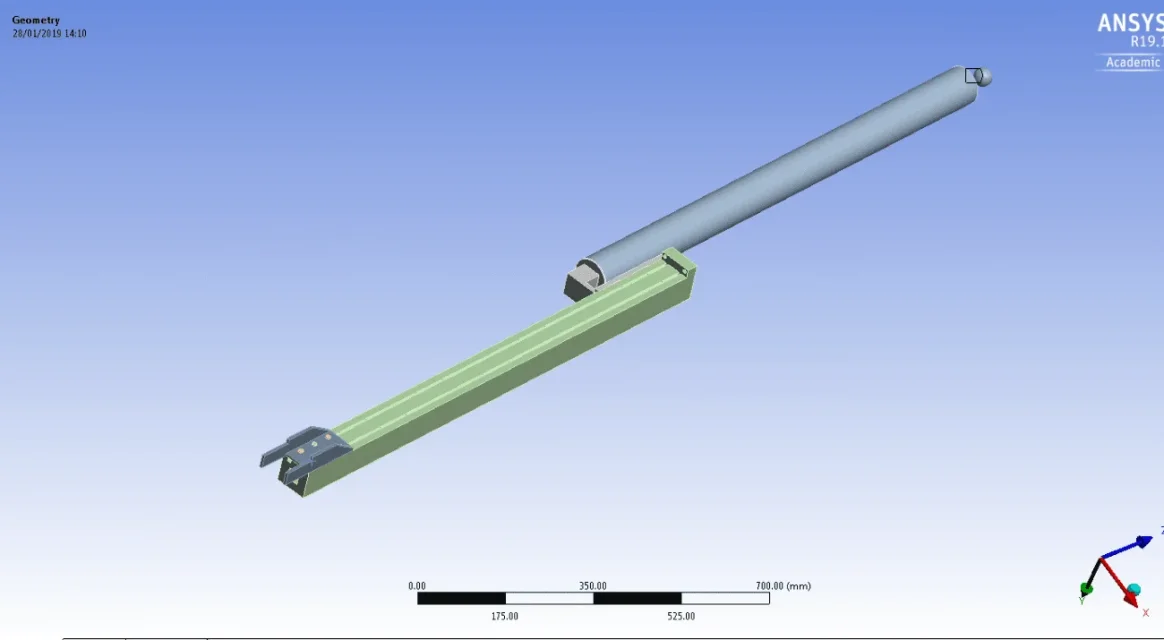
I would need your help to conduct a static structural analysis; below I expose you the problem with the help of some pictures.
The object of the simulation is a mechanical set bound by a support so that it can work as a bounce.
The only agent load is the weight of the structure.
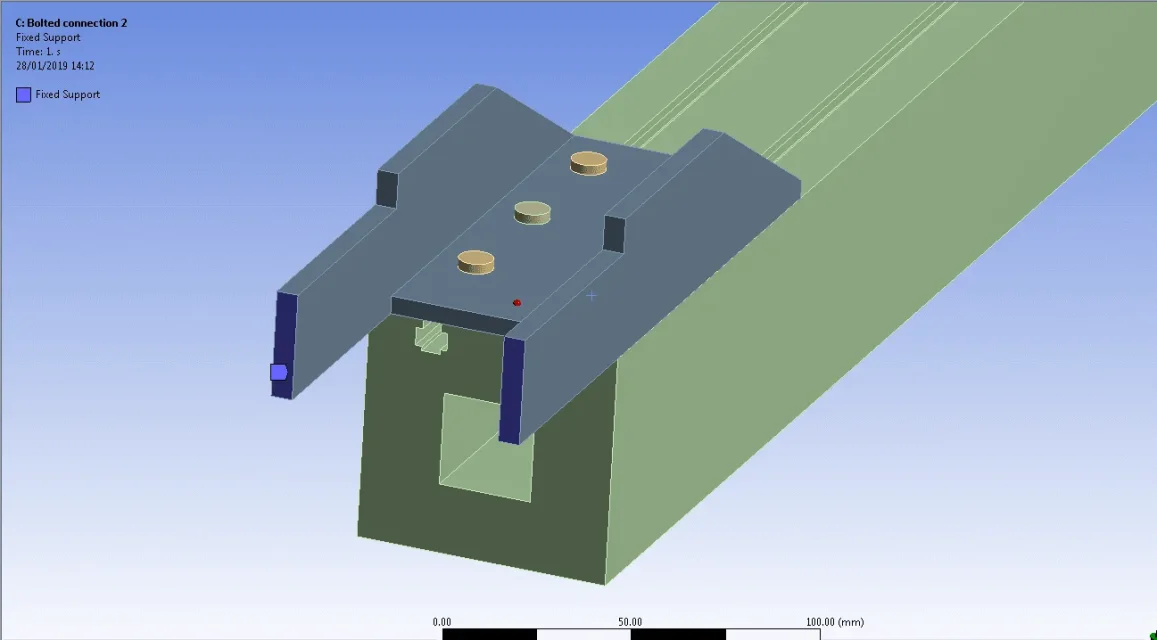
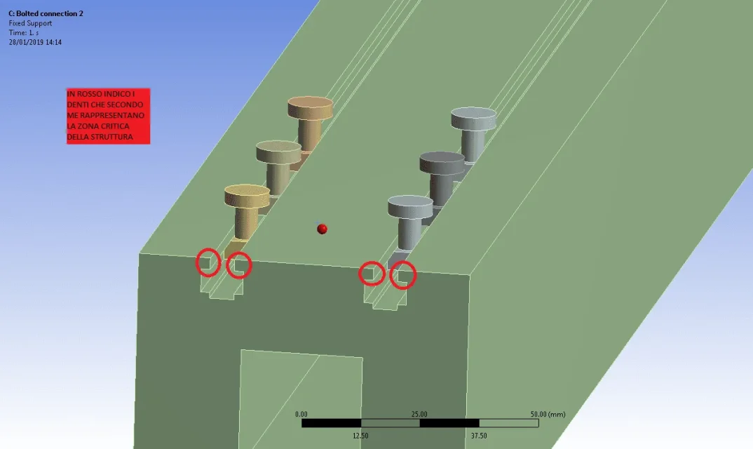
the support is connected to the underlying element by means of pins and nuts and alone must support the entire structure, which therefore tends to inflect under its own weight; the objective of the analysis is to evaluate the right length of the support plate and, therefore, the number of necessary pins so that the load is distributed without letting the integrity of the structure (in particular what worries me is the tooth of the green part that I fear is "strapped" if the number of perno/dado pairs is too low).
Specifically I would need some advice on how to manually assign contacts between the superfacts so as to simulate the aforementioned connection, since the software often generates an error that prevents the resolution stage, or stress on the screws and teeth concerned is really very low (type 16 mpa), taking into account that the entire structure weighs about 20kg.

 Thank you!
I would need your help to conduct a static structural analysis; below I expose you the problem with the help of some pictures.
The object of the simulation is a mechanical set bound by a support so that it can work as a bounce.
The only agent load is the weight of the structure.
the support is connected to the underlying element by means of pins and nuts and alone must support the entire structure, which therefore tends to inflect under its own weight; the objective of the analysis is to evaluate the right length of the support plate and, therefore, the number of necessary pins so that the load is distributed without letting the integrity of the structure (in particular what worries me is the tooth of the green part that I fear is "strapped" if the number of perno/dado pairs is too low).
Specifically I would need some advice on how to manually assign contacts between the superfacts so as to simulate the aforementioned connection, since the software often generates an error that prevents the resolution stage, or stress on the screws and teeth concerned is really very low (type 16 mpa), taking into account that the entire structure weighs about 20kg.


 Thank you!