• This forum is the machine-generated translation of www.cad3d.it/forum1 - the Italian design community. Several terms are not translated correctly.

boundary conditions per vof

  • Thread starter Thread starter walterb
  • Start date Start date

walterb

Guest
Good morning to all, I am a student of mechanical ing. who for some time has taken care of cfd.
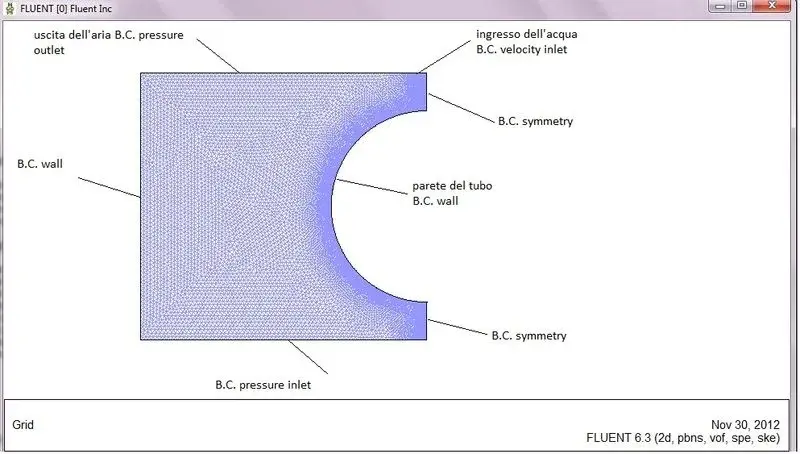
I should model a free fur in a system formed by two vertical pipes placed in communication by a circumferential compass: in the pipeline the fluid goes up and then tracise into the pipe when it meets the asola. above the thermovector fluid the volume is filled with a gas.
now : I impose an inlet velocity and a pressure outlet on the entry and exit sections of the thermovector fluid, and a pressure outlet on the section that delimites the fluid domain above, because I want the gas not to pressurize but to the ambient pressure; I have now achieved unrealistic results and most of the time the calculation diverges. I have problems with overcoming the limit for the turbulent viscosity ratio, but my mesh(gambit) has aspect ratio<9 and equiangleskew<0.4.
I tried to compute with second-order methods but it doesn't improve anything.
Would anyone give me any ideas or advice?
thanks for the collaboration.

walter
 
Bye to all,
I have not yet found the right combination, but as far as the turbulent viscosity ratio is concerned, I think I have to compromise: on the one hand I would like a decent y+, maximum 30, while on the other I would like not to see the limit on the visc.ratio.
the problem lies in the fact that trying to lower y+ I work a refinement on the walls, but this leads to a big increase in the aspect ratio, which leads behind the growing number of cells that exceed the limit.
Are you okay or am I wrong? Can you tell me how to set the height of the elements in gambit?

Thank you.

walter
 
the increase of the aspect ratio is physiological to the walls, but as the flow should be aligned with the cells should not be very welcome problems.

rather the high turbulet viscosity could make me think that you lower a great difference between the initial conditions and the final solution.

instead of a constant inlet velocity you tried to use a velocity profile (and the same for turbulent quantities) closer to the reality of a flow developed in a tube?
images
Something like that to understand. you can do or write a udf or make a very fast simulation of a tube using periodic conditions to the inlet and outlet. then when the solution went to convergence, you take the profile and you put in your real simulation.

another tip is plotting, half simulation, residuals and see where and if mesh causes problems.

Moreover, unless you want to completely solve the viscous sublayer, you can use wall function. They are usually well-tended on this type of application and allow you to use a y+ between 200 and 30. but I don't know if the same epr can fit the heat exchange. Moreover the wall refinement made by fluent is very expensive in terms of cells and does not allow control on growth factor, perhaps it is better to predict the height of the first cell at the time of meshatura
Perhaps if you place some image of the non-physical solution and mesh you can better understand what happens.

Hi.
 
the problem of turbulent viscosity I think I can solve it without particular problems; for what concerns the boundary conditions instead according to you can work? because it tends to diverge my continuity. I'm putting two pictures. .
Now I try to give him a parabolic profile. .
Thank you!
 
I have tried to put in a parabolic profile but it is not that the question has improved so much...the biggest problem apparently I have with the pressure, which assumes an unbearable values (type e+11) and consequently the speed starts for the tangent.
Is it a problem if I set an inlet and a outlet for the thermovector fluid and a pressure outlet for gas?
I mean, for the heater I have an inlet and outlet, while for the gas I impose only one outlet.. is it a problem for the continuity eq.?

Thank you.

walter
It is difficult to debug a problem on the other side of the monitor, however. . .

I would be careful to play with boundary conditions because it is extremely easy to take whistles for whistles and make sure that the imposition of unrealistic or forced bc impose a non-physical solution.

if your problem is not turbulence but pressure and speed perhaps it is the case instead of going to take a look at the various numerical methods you have chosen.

Are you talking about a transient or pseudo-steady simulation? How is multiphase set? vof geo-reconstruct or hrsc? How's the courant number?

What scheme do you use? simple, simplec or piso? what methods of discretization for gradients and pressure? and for the time?

single or double precision? if you work on multiple cores how is the domain partitioned?

as you can see there are a "thing" gazillion that can crash a simulation, not last the mesh.

multiphase is one of the most difficult fields to investigate with regard to the cfd. you don't get hurt, but you're giving a little information to be helped with profit.
 
you are perfectly right sail, but unfortunately I cannot post anything.. .
for what concerns the multiphase is set as vof, implicit (I look for the steady-state for now), implied body force..k-epsilon standard for turbulence. I have always used the simple, node-based for gradients..in simulations in general I always start with the top-order upwind, then move to the second order when I see that converges, and I do not lower the coeffs of sub-relaxation because I do not want to distort the solution, but rather I try to raise them until they bring instability.
work on one core and in single precision.
I try to give you an idea of the remains: everything remains quite flat up to a hundred iterations, then part for the tangent continuity.
If I go to see the values of pressure and speed I find things unbeatable type e+11 for pressure and e+5 for speed, also come out 30000 kg/s mass more than what enters...I hope I have given you an idea of what happens, but I understand that it is very difficult without seeing some pictures.. thank you anyway!
 
so to the eye it seems all right, try only to use cell-based for integration, at the limit I would tell you to do a test using the explicit wording of vof, should have a more defined interface. Of course it's even more expensive.

the patch to initialize the solution is done correctly?

I don't think of anything else at the moment, sorry. .
 
for the patch I define as the primary phase the gas so as to initialize then the vf for the thermovector fluid: I fill the lower part of the domain up to a quota that should not get far from the actual one of the free fur. before launching the run I visualize the contours of the vf and it is ok. under the boundary conditions for the v_inlet and the pressure_outlet liquid zone set the backflow volume fraction pairs to 1 for the secondary phase (the liquid precisely); in the gas zone on the contrary pongo 0.
I would also like to set in the pressure outlet liquid zone the backflow pressure due to the hydrostatic current (because the free fur will not be horizontal): Can you tell me some examples of udf suitable for my purpose?
Sorry I'm late, I was away from the pc.

udf to take account of hydrostatic pressure is very simple: I attach it as pdf.
 

Attachments

Bye to all,
I'm sorry for my ignorance, but I haven't been able to understand what hanging nodes are. .
Would anyone want to explain it to me or direct me where I can find a decent explanation?

Thank you.
 
Hello, I am a graduate in mechanical engineering and currently a doctorate in energy and environment systems.
I must simulate the operation of a heat exchanger, especially an evaporative capacitor.
geometry consists of a tube externally wet by a liquid film (water) and the scope of an air flow in countercurrent with the liquid itself.
condensation of the coolant inside the pipe occurs thanks to the transfer of sensitive and latent heat, due to the evaporation of water in the air. I am conducting simulations with fluent, in particular I use the multi-phase vof model.
to model the evaporation I defined a mass exchange mechanism, from the interaction panel between the phases, whose exchange coefficient is the result of a function I have implemented.
for the latent contribution instead I defined an appropriate source of energy.
I am also conducting stationary simulations, using an implicit scheme, for the turbulence model I am using the standard k-epsilon, for discretization the first order.
the simulation comes to convergence, but known that the residues have a decreasing monotonous trend, except for the continuity that presents an oscillatory trend. I am afraid that the problem lies in the boundary conditions, as, being the liquid phases and steam in countercurrent, the water output simultaneously represents the entrance of the air.
I attach an image of the computing domain for greater clarity.
would anyone have useful advice about the boundary conditions?
I would be grateful
Thank you.
Maria
 

Attachments

  • immaginejso.webp
    immaginejso.webp
    41.1 KB · Views: 2
Last edited by a moderator:

Forum statistics

Threads
44,997
Messages
339,767
Members
4
Latest member
ibt

Members online

No members online now.
Back
Top