• This forum is the machine-generated translation of www.cad3d.it/forum1 - the Italian design community. Several terms are not translated correctly.

compatibilità mesh ansys apdl

simbaf

Guest
save to all users who will complain about this debate to help me.
I just started using ansys apdl and wanted to ask you something. as I have to model a masonry building, as I do to make compatible the mesh of two elements (they are shell elements that simulate the walls) that for example si intersecano 90 degrees? (or that still don't lie on the same floor? ...and then simulate the intersection of two walls). I press that I amount geometry on ansys in iges format.
Thank you in advance!! !
 
Bye!

I think you should make sure that the joint knots between the two shell elements are consistent, I don't know if I was clear.

If I have a meshato shell element (for example, vertically) and another perpendicular to this (also meshato) you should make sure that knots in the common area to the elements are coincidental.
 
Hello! !
Yes, the point is that. the fact is that it is almost impossible to make mesh coincide manually. As I have seen that in ansys workbench there is a way that automatically makes mesh prorio coincide on the edge where the surfaces meet, it seems strange to me that this possibility can not exist even on apdl that is much more advanced as model management. Anyway thank you for the interest! ! !
 
Then I can tell you "depend". I'll explain.
all depends on how you meshato the shell elements that then intersect.
Did you do a free mesh?
a mesh map? !
 
I made a free mesh. I thought there was a "something" to be defined for example on the contact edge between the surfaces...bho? ? ?
 
Okay.
If you do a mesh free it seems normal to me that if you have no luck, nodes will never be overlaid.
to avoid this I suggest you take a look at the "lesize" command.
to understand its use well I recommend you to draw two identical and perpendicular shell elements (equal to understand that it does the command but the elements can be also different, and here the thing gets complicated).

to overcome the problem you have, in my opinion, you have to make a mesh a little more "precious" trying to make it quite uniform so that the knots of a shell and those of the orthogonal shell are coincident, or anyway, quite close.
 
hello to all, can you tell me what is the automatic way, in workbench, to make mesh knots coincide on a contact surface between two bodies?
Thank you in advance.
 
in the "geometry" module, select the two or more bodies you want to "seat" and right-click "form new part".
 
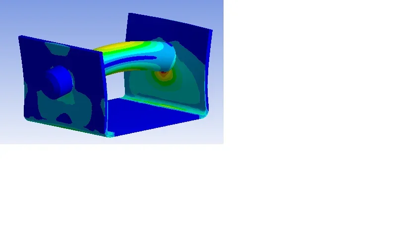
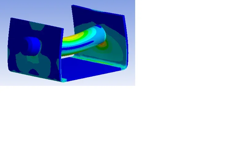
Hello stefano.garbin, thank you for the answer, but I couldn't solve it. I try to explain myself better. I noticed by randomly analyzing a larger structure (but I don't know if it's my mistake) that combining more bodies of a set the resulting voltage map is wrong. for simplicity place some images related to a simple structure (a sheet with two holes, framed at the base, and a pin). applying a force on the pin, the tension map on the sheet is always the same, while changing the direction of force:
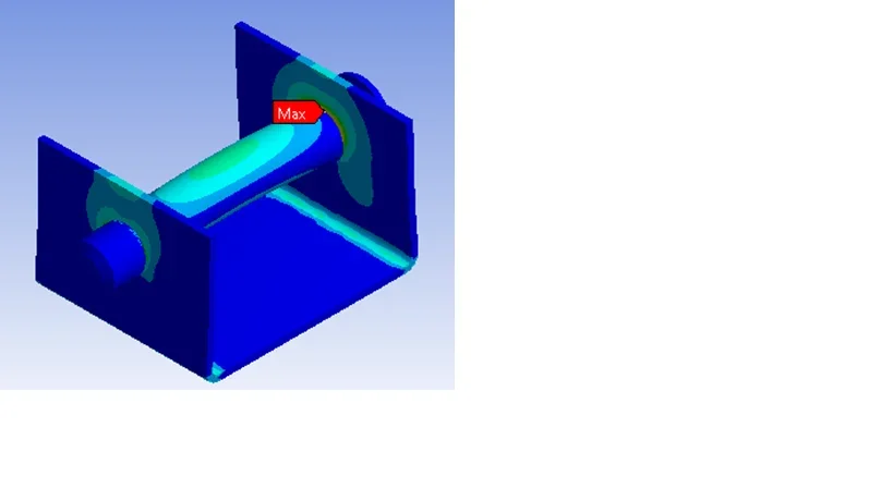
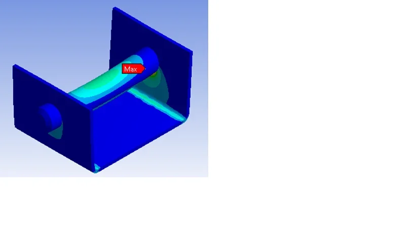
Img_1.webpImg_2.webpvice versa, if I leave the bodies separated by creating contacts without friction and leaving the pin the possibility of radial movements (one of the purposes of simulation is the verification of tensions in the holes), the voltage map appears intuitively correct:
Img_3.webpImg_4.webpThis obviously involves an increase in computing times (related to contact management). Moreover, at the end of the simulation, ansys shows the following message: “warnings generated by the solutor during the solution. Usually the problem has to do with an incorrect matrix, perhaps due to the property of the unreasonable material, a sub-vine model or a contact problem. check the results carefully. ”
use ansys 11.0. Thank you in advance!
 
the load goes towards stiffness. in the first case the pin is glued. to put in traction or compression the underlying part.
In the second case the pin works in contact. so tensions must turn around the contact area.
both analyses are perfectly correct.
 
Last edited:
possible that inverting the direction of the load, on a piece not uniform in all directions, there is no slight difference in the trend of tensions?
 
possible that inverting the direction of the load, on a piece not uniform in all directions, there is no slight difference in the trend of tensions?
I think it's showing the equivalent voltage (von mises or something), which by definition is always positive.
 
Maybe I get it. being the open sheet, in the case of glued bodies the lower part works with bending (the pin the "transcin", being glued, and the lower face of the sheet is framed), with consequent high tensions, while the upper part remains almost discharged, both with force up and with force down.
Certainly, therefore, the model with the glued bodies (being the thickness of the sheet much smaller than that of the pin, and therefore being the rigidities deeply different) is not good for this type of simulation. the model with the contact is vice versa "physically" correct: I just need to know if the "warning" that gives the solutor can affect the result or not. I believe not, since the voltage values that I get are quite close to those that are calculated with the usual rules of design, as long as I realize a regular mesh on the contact surfaces (by mapping surface mesh). What do you think?
 
interpretation is the right one. warning you must read and understand severity. Can't you open the solutor output text file to see warning?

could also be due to the fact that the pin, when in contact, is very labile and the solutor to converge uses weak springs to stabilize. the pin seems to me to have no constraint except contact.
 
hi wave, I have bound the pin with respect to the bracket with a connection that allows only radial movements (compared to the holes). However I used a short time ago by a colleague a more recent version of ansys (the 14.5) and the only warning that is generated after the simulation is related to the use of weak springs (and I think it is not a problem). What do you think?
 
provided that there are in the forum people much more experienced than me for ansys, (I use nastran). I see I give you my point of view, maybe then someone can correct if wrong.
weak springs are added by the solutor, automatically, when you realize that there are lability. They are nothing but low rigidity springs, which come on one side connected to the ground, and on the other to the knots of the element that would otherwise be labile.
I think, but I'm not sure, that the springs are added in the initial part of the contact tetration, and then decreased stiffness once the contact took shape.
Obviously, a weak spring is an external element to your model, as though it has a low stiffness, connects the model to the ground at an undesirable point and then modifies the tension pattern.
this is why the solutor from warning, warns about the use of weak springs and the potential change to results.
I think, that the result is correct and that warning is normal, but you should go deep on the wb manual and see in detail this part.

basic this the way he works: at the beginning of the solution contacts are open, and therefore the pin is labile, if it does not add springs could not solve it. once the pin went into contact, and then found a link this becomes less labile, the springs can be removed or reduced. I do not know in the specific case how ansys treats the passage from the first step (open contacts) to the last, (solution with all contacts in operation), if it modifies the stiffness of the springs or eliminates them.
greetings
wave
 

Forum statistics

Threads
44,997
Messages
339,767
Members
4
Latest member
ibt

Members online

No members online now.
Back
Top