• This forum is the machine-generated translation of www.cad3d.it/forum1 - the Italian design community. Several terms are not translated correctly.

construction in ansys of cables arranged according to parallels and meridians

  • Thread starter Thread starter Pan
  • Start date Start date

Pan

Guest
Good morning, everyone!
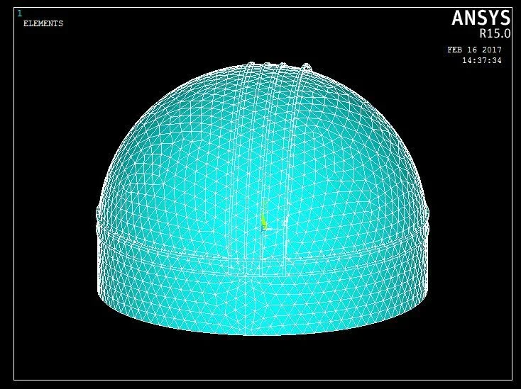
I would have a problem on ansys I created a dome with a drum and I have to lay around the cables second parallel and meridian but I do not know how to draw them, because through lines and points do not follow the trend of the dome itself. Does anyone know how I could do that?
Thank you.
 
by experience I recommend you to model these particular cases with any software cad, otherwise I would say through intersections of plans with which you generate cables. put a photo so maybe you better understand your problem.
 
by experience I recommend you to model these particular cases with any software cad, otherwise I would say through intersections of plans with which you generate cables. put a photo so maybe you better understand your problem.
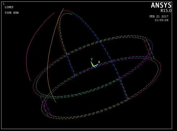
Thank you for the answer! I actually have already tried the design road in cad but importing then in ansys does not recognize the lines of the parallels and merdians, while doing everything directly in ansys I can not give the lines the curvature of the dome and I do not know how to do it.
the goal should be to have the cables arranged as parallels and meridians to be able to assign them different characteristics and see the behavior of the dome with steel cables and kevlar and make comparison.

meridiani.webpCupola.webp
 
hi pan, I'm not practical to model in apdl environment but so on two feet I would tell you to generate curves through an equation that in your case would be very simple, or if you want to follow the cad road you have to export the line file in "iges" format and you will see that ansys then recognizes you. Try and let me know how it goes.
 
hi pan, I'm not practical to model in apdl environment but so on two feet I would tell you to generate curves through an equation that in your case would be very simple, or if you want to follow the cad road you have to export the line file in "iges" format and you will see that ansys then recognizes you. Try and let me know how it goes.
thank you for the answer!! I actually tried the path of the cad but I can't extrude the lines of sundials and parallels on the dome, with the command project geometry does not bring them back to me on the dome and I don't understand why!
 
thank you for the answer!! I actually tried the path of the cad but I can't extrude the lines of sundials and parallels on the dome, with the command project geometry does not bring them back to me on the dome and I don't understand why!
hello pan, then, as my great prof of physics said: "calm and chalk". we try to go by order:

1 - first, with what elements do you want to shape the cables and the dome?
2 - What software do you use?

so you can help yourself better and effectively
 
hello pan, then, as my great prof of physics said: "calm and chalk". we try to go by order:

1 - first, with what elements do you want to shape the cables and the dome?
2 - What software do you use?

so you can help yourself better and effectively
then the dome is in masonry so a simple solid will go well to which I will then ensign in ansys the characteristics, while the cables are enough of simple lines or if you succeed with a certain diameter so as to simulate a true tie. as software use autocad.
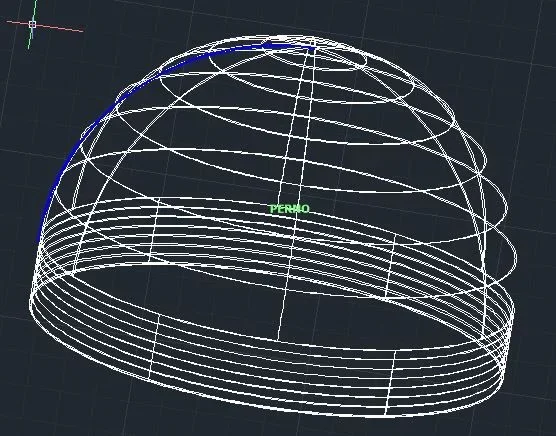
for the dome in autocad I created an arch and from that through revolution I got the outer surface of the dome, to which I added the internal one through offset of the arc of about twenty cm. However in this way I do not recognize the dome as solid but as surfaces and I do not know well how to convert them into solid.
thanks already in advance!! :smile:cupolaautocad.webp
 
Hello pan, then:

If the thickness of the dome is much smaller than the radius of the same (as I see), you should model it as a shell. As for the cables, even in this case I recommend you to use single-dimensional elements while I strongly disagree to use 3d elements as you should have a mesh with very small elements and everything would affect the system at a computational level.
to make the dome you have already solved, you just need to use the intermediate surface. when it comes to cables, it creates lines that represent the axis of the latter. for the sundials then make polar repetitions while for the parallels force the curves on floors placed at different heights of the dome.
 

Forum statistics

Threads
44,997
Messages
339,767
Members
4
Latest member
ibt

Members online

No members online now.
Back
Top