• This forum is the machine-generated translation of www.cad3d.it/forum1 - the Italian design community. Several terms are not translated correctly.

correct hull, order not correct!

Cormorano

Guest
Hello to all the naval, this is my first post. I press that I am a simple modeler and the yards with which I have to deal at most a table of a couple of meters.
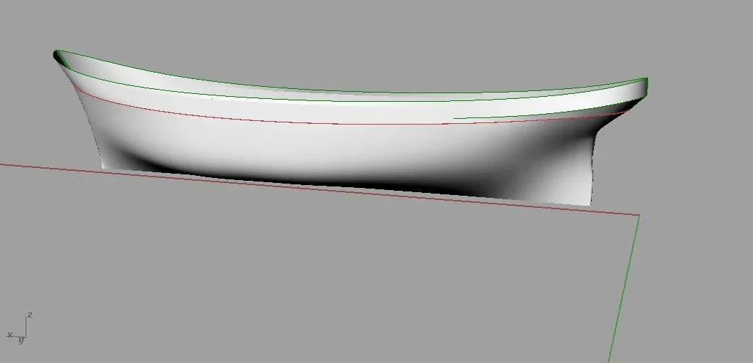
I am trying to make in rhinoceros a hull of a generic sailor (type a. vespucci or down there) and I think that more or less as form I should be there.
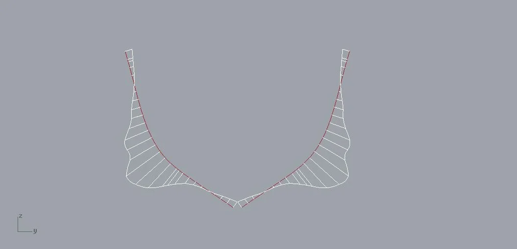
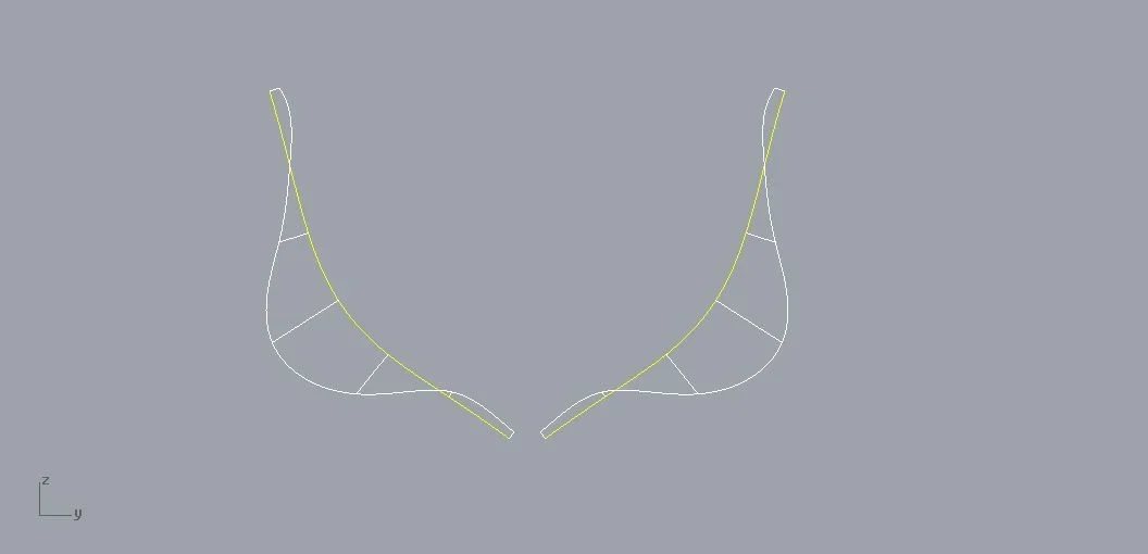
My problem is this: after modeling the hull with curves absolutely "fair" or fluent correctly, I get a surface of the hull that still seems well made. If, however, I go to slice it to have the sections of the order, the drawn curves seem far away from being in turn "fair". I have obviously displayed the curves with the appropriate scan/curve/active curve chart. Should the sections not be as fluent as the surfaces from which they were cut? Is it my mistake or maybe the result I get is fine and I could ignore the unfair course of the sections?

thanks to all those who could enlighten me.
I put in some pictures that I hope will clarify the problem.
this is the departure hull:Vista prospettica.webpthis is the section profile cut by the hull. very little fair. The white curves of the curvature analysis are quite irregular.Profilo non fair.webpThis is what I would expect, given the goodness of the hull used. this has been corrected manually, to make understand the difference between the two results. Curve lines are much more flowing.Profilo fair.webpWhat do you think?
Bye.
Horny.
 
hello and welcome to cad3d.
If we talk about the harps, I can "balance" saying that I practically play at home.
In fact, the old lady in question is permanently entrusted to our care and in particular this year will be completely modernized on the basis of a preliminary design of which my office has occupied and whose study I allow myself to define myself the author.
to a first look I would say that your hull is similar but not the same but I should verify its dimensional relationships and forms.
However, coming to your post, the problem is more on the quality of the surfaces than on the fidelity of the project therefore, being a perfect somaro of the modeling of surfaces and having never used rhino, I fear I can not be of much help.
This is a model and defining the scale (presumption 1:100 as it is a unit of more than 100m f.t.), one could trace the order of study on the basis of the real dimensions obtaining an absolutely faithful building plan.

But I know with certainty that the construction plan for model purposes is for sale (e.g. from the Bolognese shipbuilding association - http://www.anb-online.it/).
 
ahimè if the sections are wrong also the surface is wrong, although it does not seem. one of the analysis tools of a surface is in fact this. Those flexes near the belt, if not volutu, are ugly, but that trend of the curvature is not really bad. much depends also on the process of realization. If you're in control maybe you can have problems, but if you build by hand, it's probably more than good.
 
thanks for your answers. no, it's not just the broom but a similar model but much smaller (the ebe golet preserved at the milan museum - the broom hope to make it later).

the ebe has very strange curvatures and even those flexes are just like this (at least judging by the plans in my possession) but the problem is precisely the quality of the surface. what disturbs me a little is just those rather rough and inconsistent curve variations visible on the section. then, if it is the surface to have problems, there are tricks to highlight them and eliminate them? In the end, this should be the problem.

the surfaces of the hull is better to make them with the loft, with the network of curves or with what? and with what options? what final treatment can we take to have correct and fluent surfaces (and therefore sections)?
I would like to do this with a cnc. What problems could I have with curves not exactly optimized?
I know. Is there someone who solved it and can pass me some tips?

thanks and cross your fingers.
 
waiting for surface experts to intervene with their advice, allow me to make some history for the benefit of those who read.

the ebe golet brigantine was a two-seater sailing ship (trinchetto armed with quadre sails and master armed with golden sails) from 326 ton.
launched in 1921 to travel from the sa costr. nav. velieri con il nome di gullno, per il lloyd royal belge ltd. di renfrew, was purchased in 1926 by the lime and similar industries of napoli and in 1930 by a. finocchiaro di genova and renamed san giorgio. he served as a merchant ship between genovas and rogues. in March 1933 he became a school ship for the pupils nocchieri a pola and maintained this function until 1943. in 1937/38 received an auxiliary engine. in 1952 it was purchased by the military navy with the name of ebe for the school students nocchieri to the maddalena. disarmed and removed in 1959, it was disassembled in 90 parts and transported with 25 trucks to the museum of science and the technique of Milan where it was rebuilt.
for the functions of ship school nocchieri, the marina acquired ship “palinuro”, an armed golet with three trees and bompress: the trinchetto tree is to quadre sails while master and half are to golden sails, the bompress has flakes. the hull is in riveted steel.
the aircraft was launched in nantes, in bretagna in 1934, at the “anciens chantiers dubigeon” with the name “commandant louis richard” and was used for fishing and transport of cod from the docks of Terranova on behalf of the “société de peche malouines” of saint malo. in 1947 he changed shipowner and with the name “jean marc aline” was used for fishing in the Indian Ocean. given its excellent nautical and technical characteristics, in 1950 it was purchased by the Italian military navy and subjected to a series of great works of adaptation to ship school in the yards of castellamare of stabia and to the arsenal of spice. the unit entered service 16 July 1955 with the name “palinuro”; name that has been handed down for over 100 years in the Italian Navy since it was given over time to four other units. the ship “palinuro” began its new activity, as a school ship dedicated initially to the sub-official students of the categories nocchieri, port nocchieri, mechanics and motorists naval and now to the sub-capi nocchieri of the courses held at the mariscuola of the maddalena. Many are the campaigns carried out, activities that still today, it is and has been school of marine and life for many young people. it is considered one of the most beautiful and efficient “velieri d’epoca” of the fleet of “tall ships” and is always present at the great sailing events periodically taking place. "Palinur" takes its name from the ship's novice of the legendary Trojan hero who, narrates virgilius in the heeneid, was hurled into the sea, close to the helm divelto from the stern of the ship. the bow of the goletta bear depicted a splendid golden polena of the legendary nocchiero that holds to itself the rudder; this created by a workers' leader of the arsenal of spice that drew it and sculpted it in wood.

to these addresses are visible photos of the ebehttp://www.flaviobonomini.it/coppermine/displayimage.php?pid=2955http://www.flickr.com/photos/museoscienza/5189759484/http://www.forumscuoladimodellismo.com/t2876-nave-scuola-ebeannexed instead the surfaces of the harps that I made. are like yours, with "brutte curves" but, however, are the real ones, obtained from the original detector.
It is clear that an error of a few mm, although evidenced by the bending analysis, on an iron ship of 80m are influential. in the photo are evident the flexes of the real surface of the wall of the vespucci.
06-09-2013 .webpMurata.webp
 
what disturbs me a little is just those rather rough and inconsistent curve variations visible on the section. then, if it is the surface to have problems, there are tricks to highlight them and eliminate them? In the end, this should be the problem.
Since you're not working on surfaces in 'class a' you shouldn't worry too much about this, the curvature analysis tool you've activated highlights the continuity of the curvature with a certain emphasis, actually if you go to see the deviation from the generator, you'll notice that you're inside the tolerance set during the surface generation operation.
the surfaces of the hull is better to make them with the loft, with the network of curves or with what? and with what options? what final treatment can we take to have correct and fluent surfaces (and therefore sections)?
Unfortunately here there is no simple answer, both loft and networking or even sweep are options valid for generations of surfaces, the fact is that a newly created surface is rough is to be treated with successive touches, but if you are not experienced I would recommend you to stop at this point, in fact it is too easy to degenerate a surface ritoccandola, while to improve it you need the expert hand of a good "digital sculptor":
I would like to do this with a cnc. What problems could I have with curves not exactly optimized?
No one in this case. As I told you before, the surface is generated on the guide curves by an interpolation, in which tolerance is set. when performing the sections you get a further interpolation (if you do not extract an isocurva). When you pass the curve to the cam, you make a further interpolation and you get a tool path that is typically point-point. in all these passages one has to worry only to remain within an acceptable tolerance. all this does not deserve special attention until you have to do with the generation of tool paths for the creation of prints (prints) of objects with surfaces in 'class a'. I think that if we wanted to analyze the quality of the surface of the original hull of the ebe, surely we would find much wider distortions than those that could be found on your hull, obtained from the original building plan by means of digital manufacturing technologies (without removing anything to the mastery of the axe mastery of the past).

I take the opportunity to greet exatem and thank him for his always welcome historical escursus. :finger:
 
I quote everything that says paolocolombani and add the following.
what disturbs me a little is just those rather rough and inconsistent curve variations visible on the section.
the problem is probably due to the surface too complex. you have a very high number of constraints and/or a very high degree, and therefore the interpolations of which Paolocolombani speaks make you that effect there. If you had a cleaner, more natural surface, the section would also be more natural, with less control points and therefore also cleaner.
then, if it is the surface to have problems, there are tricks to highlight them and eliminate them? In the end, this should be the problem.
There are no tricks, there is only one method of work. if you work with light and clean curves and do not restrict the surface excessively, this is natural.
the surfaces of the hull is better to make them with the loft, with the network of curves or with what? and with what options? what final treatment can we take to have correct and fluent surfaces (and therefore sections)?
much depends on the software, even more on the designer's habits. There is no "right" method. I use practically only square, others work with net, they are tastes more than anything.
I would like to do this with a cnc. What problems could I have with curves not exactly optimized? I know. Is there someone who solved it and can pass me some tips?
I was talking about mould milling. in this case the surfaces must be "very" clean, any meaning has the word "very".
If you cut nc the sexes you have much less problems, because when you go to stretch out the template, this will automatically correct the small imperfections, and above all it will not follow, because it will have no way to follow, the surface you have in the cad, except in the places where it rests on the sexes.

In my opinion, to make a model, that section is more than good. try to overlay what comes from the section and what you have "correct". What is the maximum shock? a few tenths of a millimeter? Does that sound like a problem?
 
Thank you very much to all, I suspected that in fact, for my purposes, I had engaged myself on a false problem. Of course it is that however the argument is damn interesting and I would like to know the designers of the real ships (I read of carriers designed with cad) what objectives must reach to have surfaces of the hull that are adequate to shipbuilding. are there rules at the design level or at the end there is always the omino that in the yard "fit" the curves with file and lead wire?
Can someone make some light on this theme?

Thanks again. for my initial question your answers seem to me very satisfying.

horn
in the case of ships, carriers, cruise ships, etc. you do not go so much for the subtle. if the sections must obviously be "right", but macroscopic errors are also eligible for surfaces. Once you cut the sections in fact, the bandage is folded to the press and welded by hand, then the centimeter more or less depends on the hand of the carpenter rather than the skill of the cadddist. In some cases the 3d model is not even made. the building plan comes out from calculation software for stability that have no module for fairing analysis.

other world is that of the diporto. the pleasure ship is a sentimental and not purely technical object. a well-started curve on the dashboard is like the blond hedgehog of his young wife, and must be treated accordingly.
Larger boats, in aluminium or steel, are usually stunned to hide any type of soldering bugna, but here is mastery of the carpenter, we talk instead of the fiberglass boats.
the production process of these boats passes for a model, usually in wood, on which the mold is laminated. the model must be "perfect", so then it will also be the mold and various shells. models, for example in wood, can be:
- handmade
in this case the sexes are cut to control, but then the bandage is stretched manually. this means that a lower accuracy of 3d mathematics is tolerable, as long as the sections are good

- numerical control cutters
In this case the 3d mathematics must be perfect, because any defect, even small, is brought equal on the model, and there is no elasticity of the fasciame that can come to us in the aituo.

of course this is a very but very quick excursus, if you want to deepen.
 

Forum statistics

Threads
44,997
Messages
339,767
Members
4
Latest member
ibt

Members online

No members online now.

Back
Top