Mito125
Guest
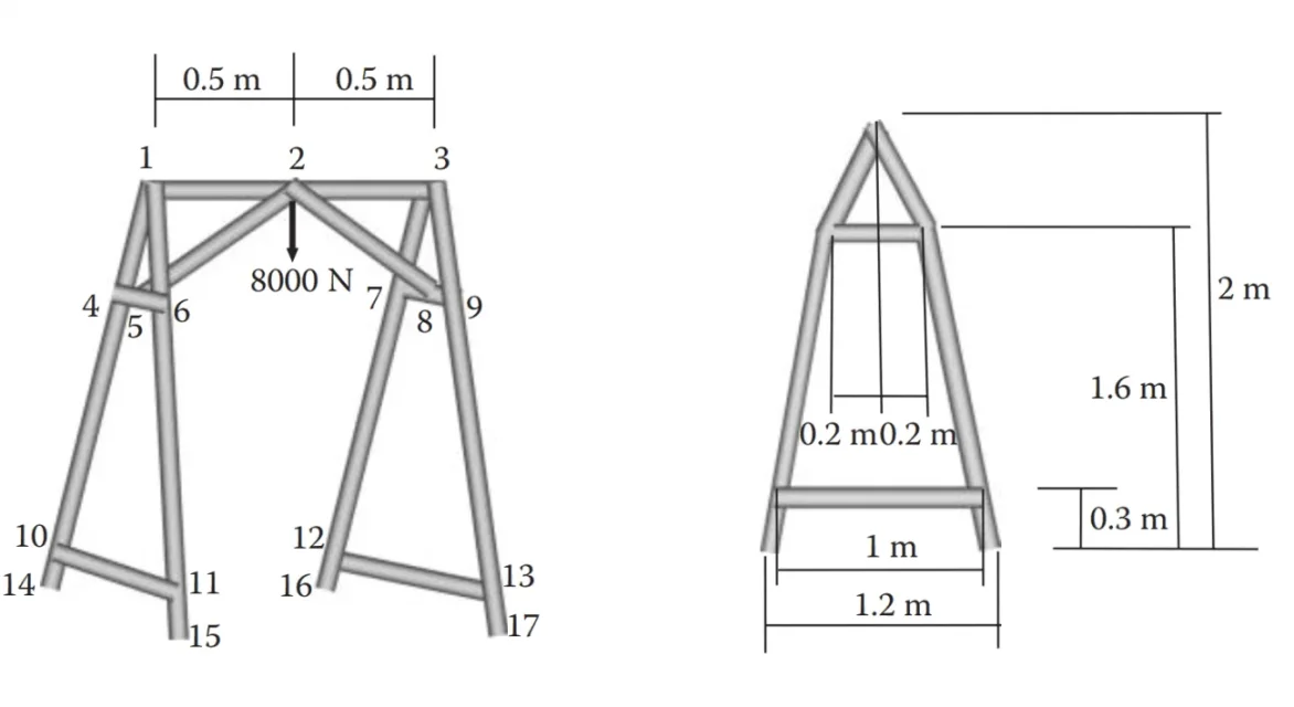
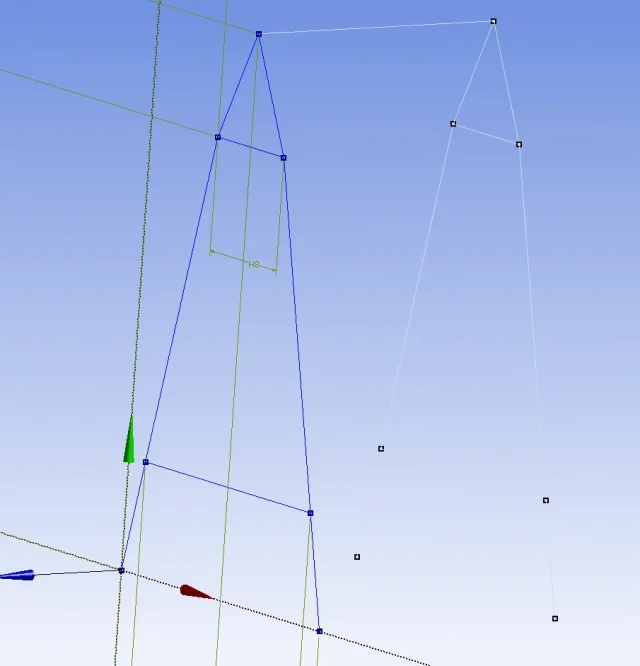
Good morning, I should create a frame for this exercise: I created the left part of the frame, then through the body transformation menu translated the part created to one meter away, I created a line by joining the points 1 and 3 indicated but I can not create the line that joins points 2 and 4 (similar 2 and 9). They are intermediate points but I can't figure out how to tell them. I am still here:
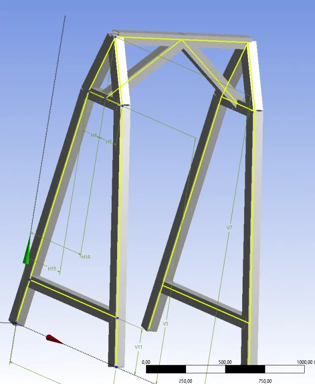
 Maybe I took the wrong way to draw the loom, maybe using the design modeler I can't do it. should you find the coordinates of all points and make a sheet with the coordinates? I think it's a little fucked up. Perhaps you should make the drawing on another cad? Thank you.
 I created the left part of the frame, then through the body transformation menu translated the part created to one meter away, I created a line by joining the points 1 and 3 indicated but I can not create the line that joins points 2 and 4 (similar 2 and 9). They are intermediate points but I can't figure out how to tell them. I am still here:
 Maybe I took the wrong way to draw the loom, maybe using the design modeler I can't do it. should you find the coordinates of all points and make a sheet with the coordinates? I think it's a little fucked up. Perhaps you should make the drawing on another cad? Thank you.
