Trial4life
Guest
Hello everyone,
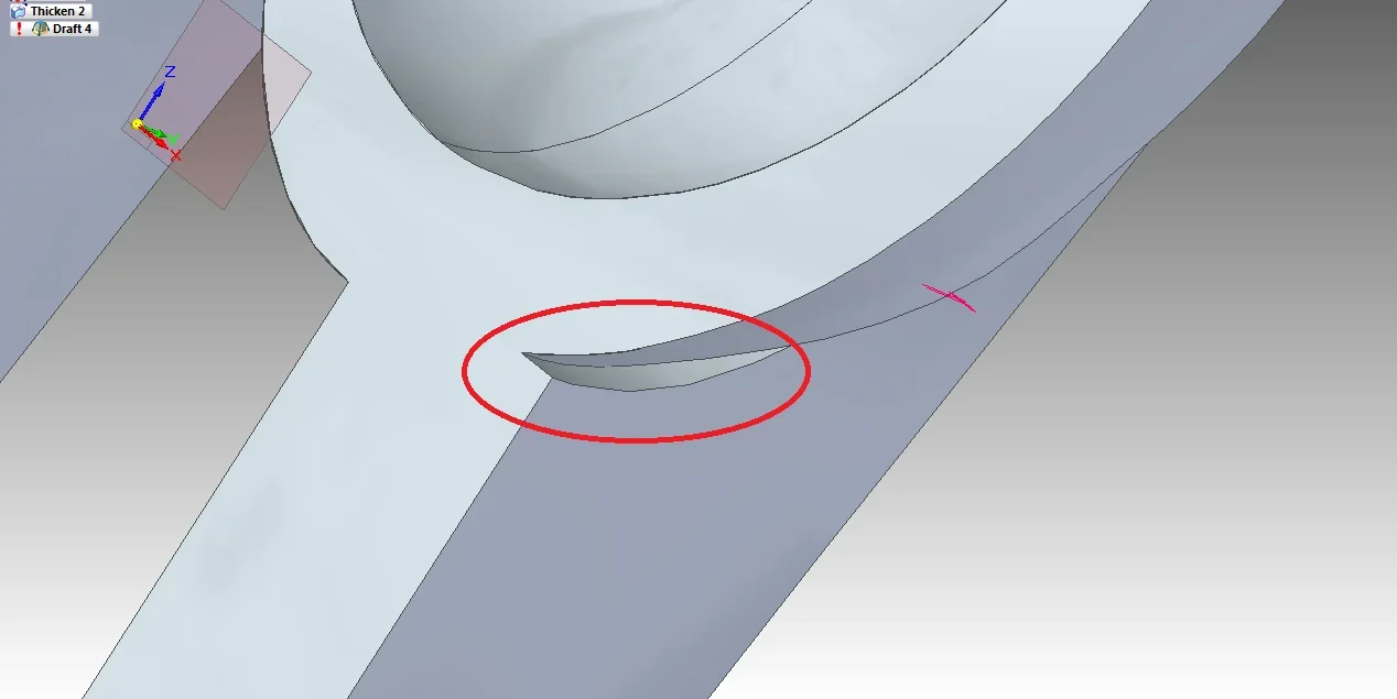
I would need to create some sform angles on a piece, or tilt the selected face of some degree than the one below. is there a simple and versatile way to do it, or should I be adding the necessary solid portion manually? I tried with the "draft" function in the "solids" section, but it gives me an error ("face/face checks fail"), probably due to the complexity of the solid (I imagine because it does not find a unique axis around which to rotate the surface). In fact, I tried the same function on a parallelepipedo, and I got the desired effect without problems. How could I do it for my piece?
I would need to create some sform angles on a piece, or tilt the selected face of some degree than the one below. is there a simple and versatile way to do it, or should I be adding the necessary solid portion manually? I tried with the "draft" function in the "solids" section, but it gives me an error ("face/face checks fail"), probably due to the complexity of the solid (I imagine because it does not find a unique axis around which to rotate the surface). In fact, I tried the same function on a parallelepipedo, and I got the desired effect without problems. How could I do it for my piece?


") in an ordered environment (not synchronous) in key points are added copies of surfaces that can be easily recalled on the draft for quotation, for example simplified views without fittings for quotation or part of the finished.
in an ordered environment (not synchronous) in key points are added copies of surfaces that can be easily recalled on the draft for quotation, for example simplified views without fittings for quotation or part of the finished.
