• This forum is the machine-generated translation of www.cad3d.it/forum1 - the Italian design community. Several terms are not translated correctly.

description profile of separate welding materials

mrdrum94

Guest
Hello everyone,
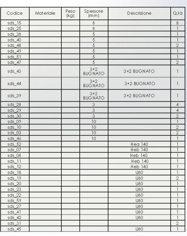
work in a metal carpentry company and it is customary to use assemblies consisting of commercial profiles and molded plate. to date the insertion of the profile description in the separate materials has been manual. I would like to know if there is an automatic way to enter the profile type directly in the table "different materials" without resorting to separate cutting and distinct materials with recesses.
Thank you.
 
do you mean that instead of using multibody parts and structural members do every single piece as part and then bind everything together?
If so, except you can use a pdm of which I am ignorant and therefore I do not pronounce, I think that the only solution is to make a model for every type of profile already with the desccritions compiled in the properties.
I think you hurt yourself by not exploiting the potential of the software, but you will have your good reasons. . .
 
if you use the multibody you have to create the templars in the welding module where there are or various tubulars or drawn the variables like the original ones of solidworks.
 
do you mean that instead of using multibody parts and structural members do every single piece as part and then bind everything together?
If so, except you can use a pdm of which I am ignorant and therefore I do not pronounce, I think that the only solution is to make a model for every type of profile already with the desccritions compiled in the properties.
I think you hurt yourself by not exploiting the potential of the software, but you will have your good reasons. . .
Hello, thank you for the answer. Then I'll explain how our design process is. we take as an example a h profile on whose ends has plates. we create an axieme consisting of the h and the two plates and all these components are encoded. After that, the next step is to pass everything to the plasma cutting department. We create a distinct material that includes the codes and thicknesses of the plates so that the material can be properly worked.
Is there a method of doing this with multibody parts?
 
Of course.
the profiles used in the creation of structural members are to all effects of sketches in part files. the properties of these files will be those that will appear in the separate cut. then compile them carefully you can have profile description, company code and how much that profile identifies. Moreover solidworks processes independently profile length and cutting angles for inks.
of course to do what you want you must alwaysand, or almost, use the modeling through the welding module, otherwise you will have to fill out the properties in the cutting distinct.
from the multibody can also be extrapolated every single body that will become a separate part, but always linked to the original therefore the changes made on the original will be reflected on that exported which in turn can be modified (closed the holes to be done by car for example) without interfering with the other.
I'll give you a little example
View attachment 41815
 
Hello, thank you for the answer. Then I'll explain how our design process is. we take as an example a h profile on whose ends has plates. we create an axieme consisting of the h and the two plates and all these components are encoded. After that, the next step is to pass everything to the plasma cutting department. We create a distinct material that includes the codes and thicknesses of the plates so that the material can be properly worked.


Is there a method of doing this with multibody parts?
bad way to work. but at least the original license you have solidworks? But you never did the course? but how is it possible that in Italy it did not evolve when the whole world was driving?

Are you sure that solidworks is suitable for your work? and your coding is good and makes sense?

have you thought to codify the design of the electro-welded carpentry and simply to number all the multibody details that make it up?


I think there's some basic analysis missing.
 
Unfortunately we have very few standard components. For example, a welded element like what you sent me could have non rectangular plates but shaped when necessary. We also need to make a distinct component to be able to switch to the cutting machines for the next processing (e.g.
 

Attachments

  • Cattura.webp
    Cattura.webp
    44.4 KB · Views: 9
I'm sorry that the question I asked for is too trivial. Thank you so much for your answer but I do even less.
Thank you.
 
draw the plate in that way so that you complete the separate cut, then the templates, the holes, you do what you want; at that point you enter the properties of the body and you put that notes you want (bugnated, shaped, bent... )

the distinct components is what you see in the design... What's the difference with yours?
Of course that if a 100x100x10 smooth plate has a code, perforated has another one, shaped has another you have no alternative but to fill in by hand.
I see heb140 with different codes. . .
 
basically to make a multibody part with different profiles and plates should I create a part of library for each plate?
 

Forum statistics

Threads
44,997
Messages
339,767
Members
4
Latest member
ibt

Members online

No members online now.
Back
Top