IlConte94
Guest
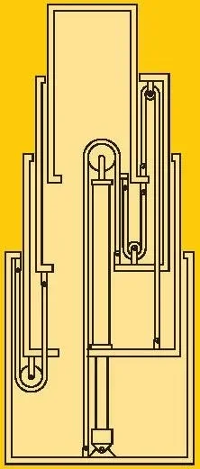
Hello everyone, I am new to the forum and although I am still a student of the mechanical engineering master I preferred to post in this section since my (or rather my) questions concern a teaching project assigned to us for an exam but that is to all effects a complete project. as from title we must design in group (but we are only 2 of which I address "design", the other person is "energetic") a vertical telescopic lifting platform like the following: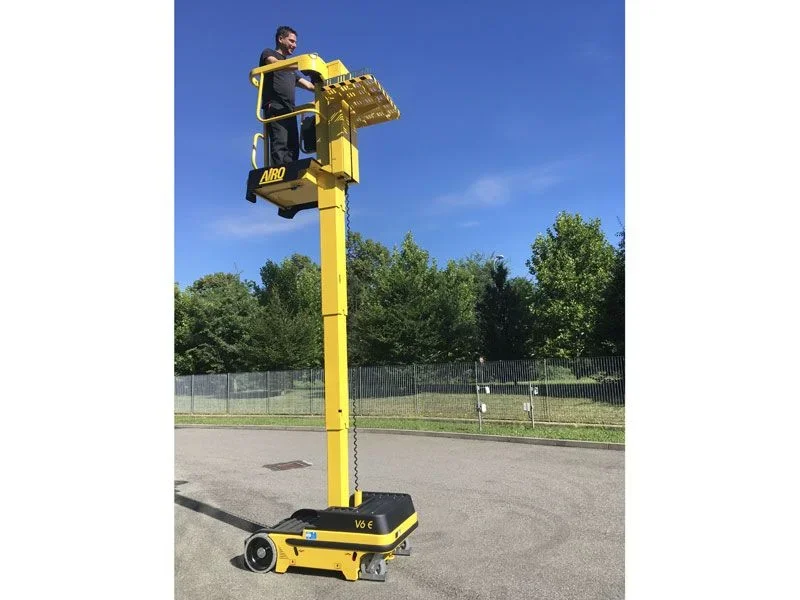 I also link the site of this machine to show you the technical specifications: https://www.topcarsrl.com/dettaglio-prodotto.php?id=14the first problem is that the professor has told us to do the technical specifications, however, by imposing some very unlikely stakes: the machine must be for interior (like the one in figure), to be closed to be able to pass in the doors of the industrial warehouses (then max 2m height) but to be extended to at least (underline!) 10 meters of working height against the 3.5 of this! This already poses an obvious problem of achievement and I wanted to know if it is technically feasible.
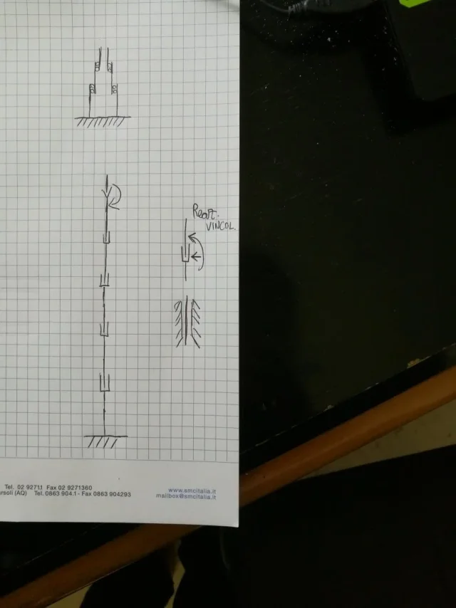
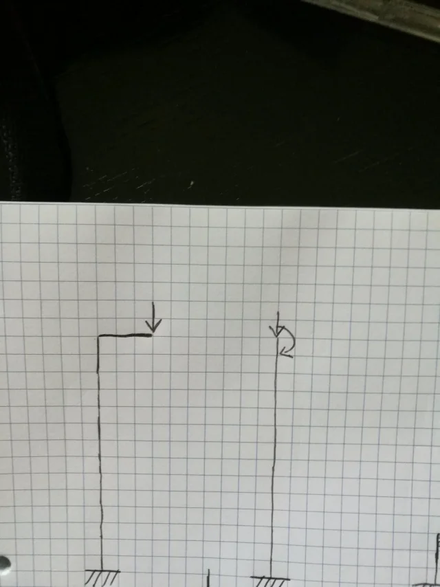
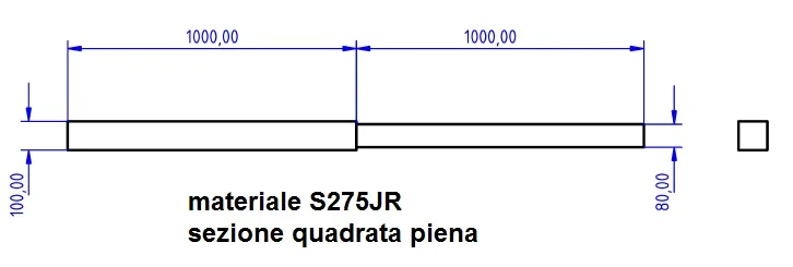
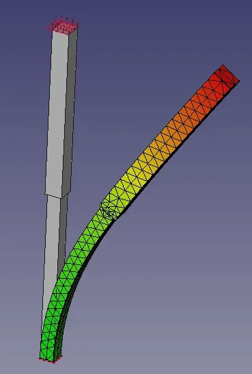
the design must be complete, in the structural kinematic sense, cad drawings of every detail and fem analysis of the individual parts and the complex with particular emphasis on the extendable column. In addition I almost forgot dynamic analysis (example tipping problem etc.). now having knowledge notionistic from the triennial (as I think happens a little in all of Italy) both of science of the buildings and of applied mechanics that of construction of machines, are not able for example to "see the machine as a beam" with constraints, loads, to predict to eye how they exchange the forces (for example to dispose of skates between the swives), so I do not know practically from where to begin. I think that you should start from a rudimentary lifting scheme (there must be a hydraulic piston in the bottom that pushes the slender and then others should parade to follow through a system of carrucoles and already preview the position inside the swires or between them seems to me a problematic not of little account at the level of encumbrance.. . )
I mean, the situation is pretty messed up. probably the fault is also mine that I did not study well the basic subjects (my priority was to graduate immediately to the three) but the very antiquated teaching certainly does not help... In addition I am learning cad and fem (ansys) software practically alone since the exam previews its use also pushed but there are no dedicated courses except perhaps that of assisted design (where however the emphasis is on mathematical theory as usual... )
if someone is able to help me even with some point I thank him in advance and maybe after I also make him a small monument! Thank you!
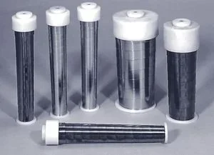
p.s: a detail that I have forgotten is that the threads can be as in figure from the smallest in the bottom to the largest in the top or vice versa from the largest in the bottom to the smallest in the top: the professor left us free choice but he said that in case we do it with the smallest down he wants a justification to the choice and it was not good to hear: "We have seen that they are generally made like this! " but we have also tried without success to think it was due to any advantages for the hydraulic system. . .
p.p:s: the exam did not write it but it is "construction of machines say 2" since the three-year period was "constructive elements"
 I also link the site of this machine to show you the technical specifications: https://www.topcarsrl.com/dettaglio-prodotto.php?id=14the first problem is that the professor has told us to do the technical specifications, however, by imposing some very unlikely stakes: the machine must be for interior (like the one in figure), to be closed to be able to pass in the doors of the industrial warehouses (then max 2m height) but to be extended to at least (underline!) 10 meters of working height against the 3.5 of this! This already poses an obvious problem of achievement and I wanted to know if it is technically feasible.
the design must be complete, in the structural kinematic sense, cad drawings of every detail and fem analysis of the individual parts and the complex with particular emphasis on the extendable column. In addition I almost forgot dynamic analysis (example tipping problem etc.). now having knowledge notionistic from the triennial (as I think happens a little in all of Italy) both of science of the buildings and of applied mechanics that of construction of machines, are not able for example to "see the machine as a beam" with constraints, loads, to predict to eye how they exchange the forces (for example to dispose of skates between the swives), so I do not know practically from where to begin. I think that you should start from a rudimentary lifting scheme (there must be a hydraulic piston in the bottom that pushes the slender and then others should parade to follow through a system of carrucoles and already preview the position inside the swires or between them seems to me a problematic not of little account at the level of encumbrance.. . )
I mean, the situation is pretty messed up. probably the fault is also mine that I did not study well the basic subjects (my priority was to graduate immediately to the three) but the very antiquated teaching certainly does not help... In addition I am learning cad and fem (ansys) software practically alone since the exam previews its use also pushed but there are no dedicated courses except perhaps that of assisted design (where however the emphasis is on mathematical theory as usual... )
if someone is able to help me even with some point I thank him in advance and maybe after I also make him a small monument! Thank you!
p.s: a detail that I have forgotten is that the threads can be as in figure from the smallest in the bottom to the largest in the top or vice versa from the largest in the bottom to the smallest in the top: the professor left us free choice but he said that in case we do it with the smallest down he wants a justification to the choice and it was not good to hear: "We have seen that they are generally made like this!
p.p:s: the exam did not write it but it is "construction of machines say 2" since the three-year period was "constructive elements"

