Francesca Pistorio
Guest
Hello, everyone!
I'm Franciscan and I'm writing because I need advice about a doubt I can't solve.
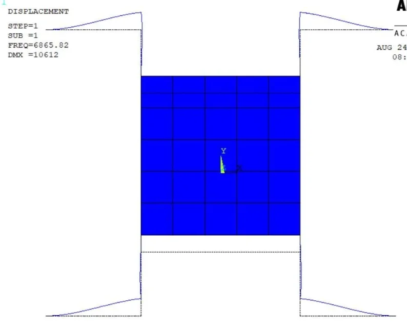
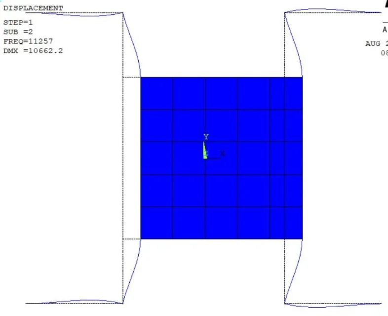
I need to model in ansys (especially I am using apdl) a mems gyroscope and I started with a really simple design, so as to simplify my problem as much as possible. It is a simple plate suspended through 4 beams to "l" . I attach an image at the bottom for greater understanding.
Since the structure is thin enough, I had in mind to use shell181 elements to shape the central plate and beam188 elements for beams. The beam 188 helmets and shell 181 both have 6 degrees of freedom, so I thought that, to connect them together, it would be enough to share the node to the interface. However, I fear that my analysis is incongruent, since shell elements do not have rigidity around the perpendicular axis on the plane where they lie.
despite this "dubbio", I tried to perform a modal analysis in order to determine the own frequencies of the structure. the problem is that, using few elements to build the mesh of the central plate, the results that I get are quite close to the theoretical ones. a much more fine mesh instead, leads drastically to a greater error. I can't explain this, but I would have expected the opposite. that is due to the wrong connection between beam and shell?
attached I insert my code apdl. I hope someone can give me advice.
Thank you and a dear greeting.
Franciscan
I'm Franciscan and I'm writing because I need advice about a doubt I can't solve.
I need to model in ansys (especially I am using apdl) a mems gyroscope and I started with a really simple design, so as to simplify my problem as much as possible. It is a simple plate suspended through 4 beams to "l" . I attach an image at the bottom for greater understanding.
Since the structure is thin enough, I had in mind to use shell181 elements to shape the central plate and beam188 elements for beams. The beam 188 helmets and shell 181 both have 6 degrees of freedom, so I thought that, to connect them together, it would be enough to share the node to the interface. However, I fear that my analysis is incongruent, since shell elements do not have rigidity around the perpendicular axis on the plane where they lie.
despite this "dubbio", I tried to perform a modal analysis in order to determine the own frequencies of the structure. the problem is that, using few elements to build the mesh of the central plate, the results that I get are quite close to the theoretical ones. a much more fine mesh instead, leads drastically to a greater error. I can't explain this, but I would have expected the opposite. that is due to the wrong connection between beam and shell?
attached I insert my code apdl. I hope someone can give me advice.
Thank you and a dear greeting.
Franciscan