LeoVenuti93
Guest
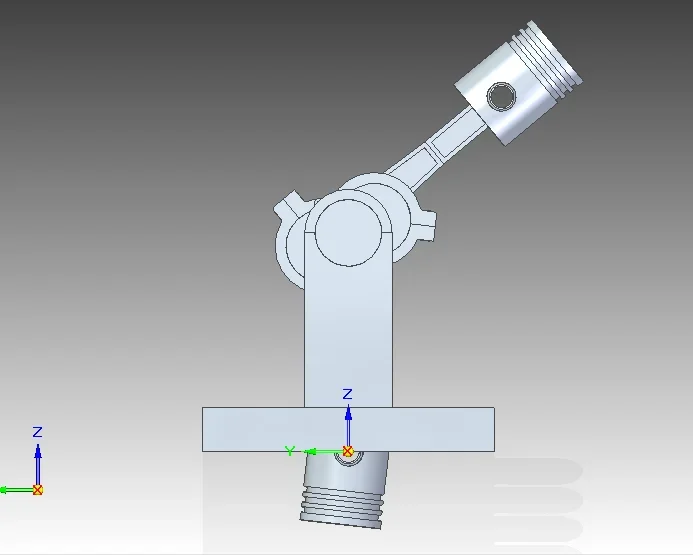
Hello everyone, I am a mechanical engineering student and I have to face a cad exam with solid edge, unfortunately online there are not many tutorials and I started with a simplified project of the v8 engine, drawn by solidworks: https://www.youtube.com/watch?v=cvile1ng63kI have performed all the components of the tutorial, and at the time of assembly I can not well and intuitively mount the various components. my first question is whether it is wrong to model in synchronous and in order and to compose a set with components deriving from the two different types of processing. the second question: why is assembly simple and intuitive in solidworks?
thanks in advance!
cordial greetings
thanks in advance!
cordial greetings
")
