• This forum is the machine-generated translation of www.cad3d.it/forum1 - the Italian design community. Several terms are not translated correctly.

gear profile

CAT_man

Guest
Good evening to all, after searching and searching I am forced to open a new discussion.

I have to draw a gear with n teeth and x module, then I will go to fix these values, but with pressure angle of 20°, how do I draw the profile of the correct tooth? so that then this can be either milled or sent to laser cutting?

I hope to have been clear in my request, I thank you in advance all of you:
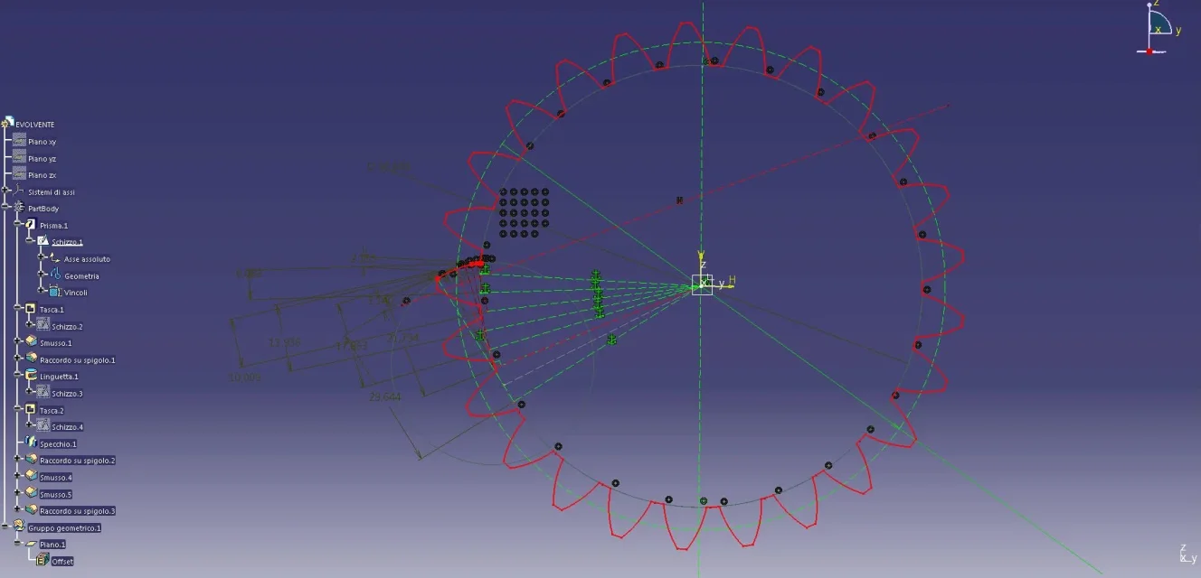
it's quite simple the tooth you build it with the evolved in a sketch then according to the number of teeth you create the wheel always in sketch
and eventually create the solid.
Greetings
 
azz, it seems very simple as you described it. . .
Let us start from the evolved and try to draw it:)
 
Hi.
we go by degrees, send you an image of how you can draw an evolved, it is clear more points put and more the tooth profile
You're being precise.
If you don't know how to build an evolved one, just a book of dense wheels or go on the internet and find it.
decide the module, the number of teeth then start with the first point of the evolver from module/2 and start.
I hope you've been helpedevolv1.webp
 
Good evening to all, after searching and searching I am forced to open a new discussion.

I have to draw a gear with n teeth and x module, then I will go to fix these values, but with pressure angle of 20°, how do I draw the profile of the correct tooth? so that then this can be either milled or sent to laser cutting?

I hope to have been clear in my request, I thank you in advance all of you:
Go on. www.me-bac.com and create the wheel dxf by inserting the desired parameters!
 
hi maybe I don't understand why you have to create a perfect 3d model, unless in the workshop they work with the cam.
I think it is enough that you create your toothed wheel you draw the quoti with all the parameters for the construction that will serve the miller for the construction.
 
since you are a user "software: autocad" the fastest way is to use one of the many macro autolisp in the network to draw the fingerprint of the toothed wheel, then from dxf or dwg it will be easy to export to the cam. since there is no primitive in any cad to correctly define the evolved, if not the definition of the mathematical function, the export from dxf or dwg will define you a tangline. sin that the laser only processes the arc function (it doesn't understand anything else ...), so when you carry it you hold a decidedly high precision. Bye.
 

Forum statistics

Threads
44,997
Messages
339,767
Members
4
Latest member
ibt

Members online

No members online now.
Back
Top