Good morning.
it is not clear what you are using of ansys, in particular:
-ansys workbench mechanical
-ansys apdl
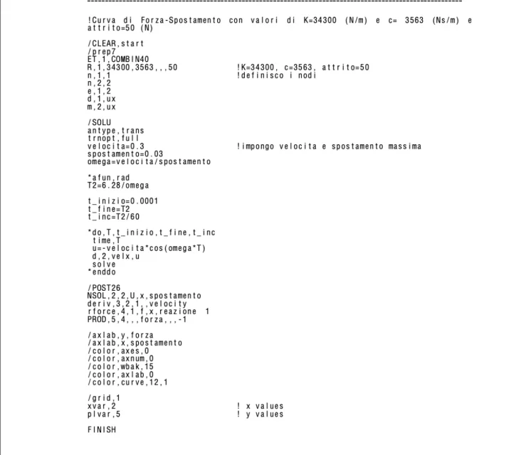
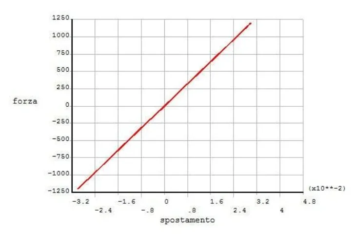
in ansys apdl the combin40 command enters the \prep7 (where you define geomtria), then you will have a test file that loads from time to time and launches to make your simulation.
on ansys workbench mechanical instead you have to press with the right button above the individual sections (see geometry, results etc.) and you will appear, in the drop-down menu, a logo with a sort of white sheet with a red c. clicking on that icon opens a text file that allows you to enter the commands manually, there you can put the combin40 command.
Maybe if you give us more information also other more experienced users of me can help you.
to this
link you can find all the information about the combin40 element