Arhad
Guest
ahimè I received this sheet printed by a pdf, which I can not even find and I would like to understand how it is possible to do it, I checked online resources and everything but I don’t even know how to do it.
exercise
sizing and static verification of a welded flange for hydraulic cylinder
object.
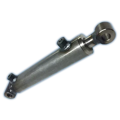
an adjustable hydraulic cylinder must be applied to a static and fatigue test counter on industrial components.
for the maximum versatility of the system, it is assumed to want to perform tests with maximum forces exeroted from the cylinder both in shooting and in thrust. Moreover, it is assumed that the cylinder is in horizontal and vertical direction, and in any intermediate position between 0° and 90° on the horizontal.
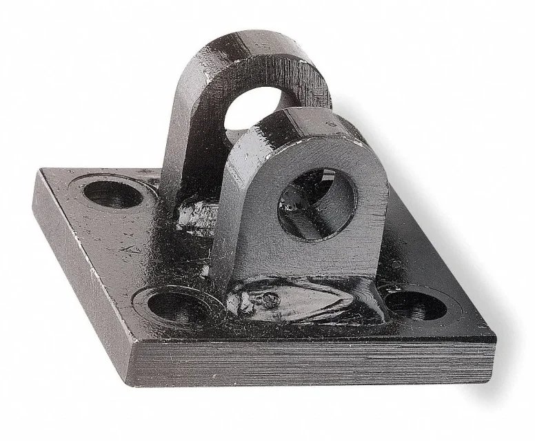
Suppose you want to connect the cylinder to the counter with a fixed zipper applied to the back bottom, with bb configuration of the figure of page 1 attached 1.
the maximum rated load values to be applied are p [kN]=~14 kn, feed pressure p [bar]=100 bar and piston run is l [mm]=300mm.
data already decided
is required:
•choice of the cylinder adapted to the data provided, in terms of aleage and stem diameter.
choice stem diameter from stroke l and load p ( diagram p. 2 attached 1)
at the counter.
• Static verification of welded flange and welds with static safety coeff. vs. 3, in the two intermediate positions 0° and 90° and at least one intermediate
•checks the bolted connection in the two extreme positions 0° and 90° and at least in an intermediate, with static safety coeffs vs > 2.
• functional set design for cylinder and flange with indication of the cylinder end action field.
•constructive design of the welded flange with indication of the processing and tolerances and with distinct pieces and materials of the connection.
exercise
sizing and static verification of a welded flange for hydraulic cylinder
object.
an adjustable hydraulic cylinder must be applied to a static and fatigue test counter on industrial components.
for the maximum versatility of the system, it is assumed to want to perform tests with maximum forces exeroted from the cylinder both in shooting and in thrust. Moreover, it is assumed that the cylinder is in horizontal and vertical direction, and in any intermediate position between 0° and 90° on the horizontal.
Suppose you want to connect the cylinder to the counter with a fixed zipper applied to the back bottom, with bb configuration of the figure of page 1 attached 1.
the maximum rated load values to be applied are p [kN]=~14 kn, feed pressure p [bar]=100 bar and piston run is l [mm]=300mm.
data already decided
is required:
•choice of the cylinder adapted to the data provided, in terms of aleage and stem diameter.
choice stem diameter from stroke l and load p ( diagram p. 2 attached 1)
- choice alesaggio cylinder starting from the stem diameter, operating pressure and p load
(Table 3 Annex 1) - valuation in bulk and perri to the cylinder bottom from the tables of page 4,5 attached no1.
at the counter.
• Static verification of welded flange and welds with static safety coeff. vs. 3, in the two intermediate positions 0° and 90° and at least one intermediate
•checks the bolted connection in the two extreme positions 0° and 90° and at least in an intermediate, with static safety coeffs vs > 2.
• functional set design for cylinder and flange with indication of the cylinder end action field.
•constructive design of the welded flange with indication of the processing and tolerances and with distinct pieces and materials of the connection.


