davide.1914
Guest
Hello everyone, I am new to the forum, I write you why I hope someone can solve my problem in ansys.
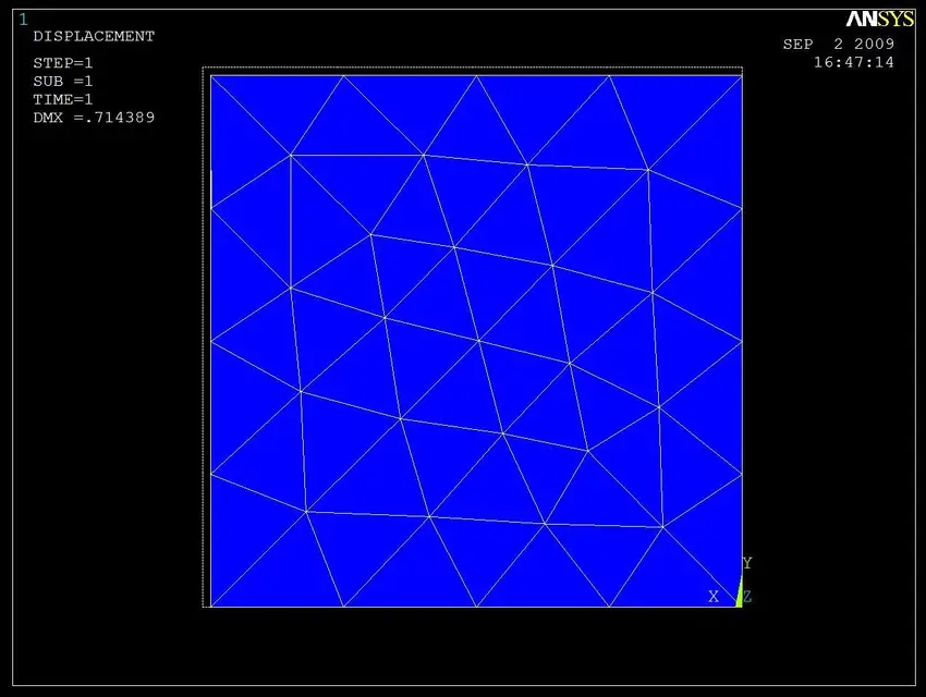
I have done two tests of a solid traction subject, one with the only constraints in the direction of the load on surface opposite to that loaded, and the second also binding two consecutive sides of the bound surface so that the orthogonal deformation to each of them respectively is prevented.
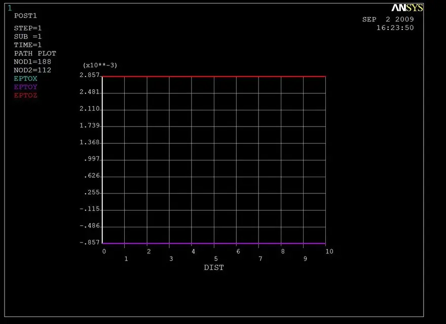
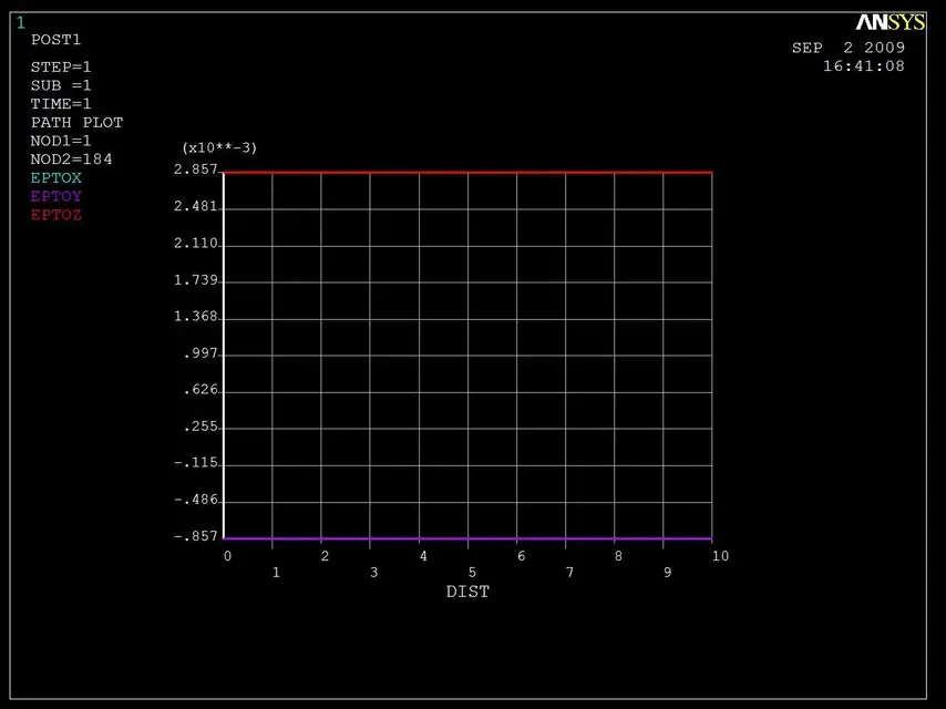
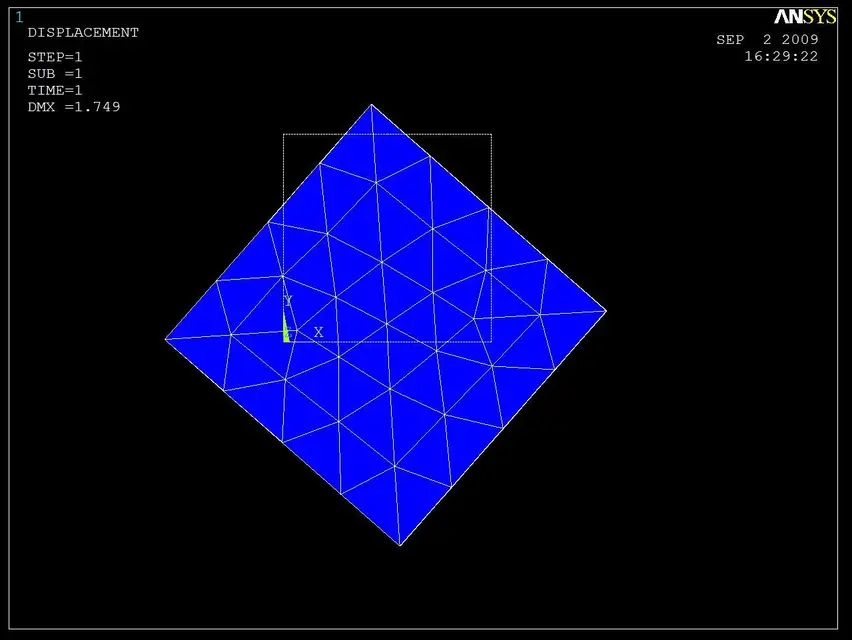
before the simulations I made the calculations love of the above tensile prism (the classic traction test), and the results of these are coincident with the results produced by ansys in both simulations; it is true that the numerical results of deformations and tensions are equal both for the two analyses and for the analytical calculations, but the graphical representations produced by ansys in the case of simulation with the only constraints in the direction of the load are incorrect, because the solid is rotated around the longitudinal axis (parallel to the direction of application of the load), which should not exist, and the transversal dimensions are increased instead of imagine the consequences in an analysis with more bodies and contact elements.
using different types of elements the dysfunction varies, it can happen that it is a solid translation on the plane containing the bound face.
in the second simulation by introducing the constraints that really should not exist, even graphic representation goes to place.
at this point is the problem of having to put these constraints into more complex simulations, where and how do they place? How do you know that?
or is it a software dysfunction that causes my problem?
or am I wrong something in defining the problem?
Please anyone to help me, thank you.
I have done two tests of a solid traction subject, one with the only constraints in the direction of the load on surface opposite to that loaded, and the second also binding two consecutive sides of the bound surface so that the orthogonal deformation to each of them respectively is prevented.
before the simulations I made the calculations love of the above tensile prism (the classic traction test), and the results of these are coincident with the results produced by ansys in both simulations; it is true that the numerical results of deformations and tensions are equal both for the two analyses and for the analytical calculations, but the graphical representations produced by ansys in the case of simulation with the only constraints in the direction of the load are incorrect, because the solid is rotated around the longitudinal axis (parallel to the direction of application of the load), which should not exist, and the transversal dimensions are increased instead of imagine the consequences in an analysis with more bodies and contact elements.
using different types of elements the dysfunction varies, it can happen that it is a solid translation on the plane containing the bound face.
in the second simulation by introducing the constraints that really should not exist, even graphic representation goes to place.
at this point is the problem of having to put these constraints into more complex simulations, where and how do they place? How do you know that?
or is it a software dysfunction that causes my problem?
or am I wrong something in defining the problem?
Please anyone to help me, thank you.
Attachments
Last edited: