• This forum is the machine-generated translation of www.cad3d.it/forum1 - the Italian design community. Several terms are not translated correctly.

information on bearings

  • Thread starter Thread starter J ax
  • Start date Start date

J ax

Guest
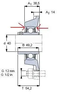
Hello, for an exam I have to dimension and draw a trinciasarmenti. on the two sides of the shaft where the decks are connected I thought I would install two bearings of this type
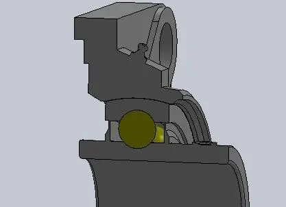
http://www.skf.com/skf/productcatal...indowname=null&perfid=212701&prodid=212701040They are bearings that have already a support and the trincias I have seen have all bearings of this type. But there is a problem, that in one of the 2 bearings, I must block the outer ring axially and from the figure it seems that it is not blocked, you confirm it to me?
If so, how could I block the outer ring?
or do you recommend not to use these bearings with the support already?

Thank you.
 
But on the sides of the outer ring there is nothing, the concavity binds axially only the central part of the outer ring (I hope to be explained well), okay the same?
 
But on the sides of the outer ring there is nothing, the concavity binds axially only the central part of the outer ring (I hope to be explained well), okay the same?
From the cinematic point of view that bearing is a spherical hinge. if then leave the free tree to slide inside the inner ring becomes spherical zipper + cart.
 
But on the sides of the outer ring there is nothing, the concavity binds axially only the central part of the outer ring (I hope to be explained well), okay the same?
I have no idea what you're saying, but as confirmed as a hunter, it's all right.

Hi.
 
What I wanted to say is that usually to block the outer ring axially, you put something on the sides of the outer ring, that is, something on the right and something on the left, while here on the side there is nothing. on the attached image I put the arrows where I want to indicate that there is nothing
 

Attachments

  • productImage.webp
    productImage.webp
    8.1 KB · Views: 32
I press that I have never had a chance to confront this type of bearing.
you don't have to block anything, the 4 holes in the flange are sufficient. the toroidal seat of the outer ring serves to make sure it is solid with the flange.

at most you have to worry about tightening the two m8 screws with the recommended torque to avoid the crawling of the tree in the inner ring.

please the others to correct me in case you said festive.. I don't even know how it works.
 
What I wanted to say is that usually to block the outer ring axially, you put something on the sides of the outer ring, that is, something on the right and something on the left, while here on the side there is nothing. on the attached image I put the arrows where I want to indicate that there is nothing
bon, now it is clear, quiet, the spherical seat performs well to the axial bond function of the outer ring.

Hi.
 
It's a classic zipper. radial and axial constraints, but allows rotations. care axially to the limits of the bearing.
 

Sorry I was also a student in engineering, see that the answer is among the meanders of the notes that the professor recommends you, see every professor has a fix for a topic, just look at them in examination induction locations and the questions will be redundant.
sometimes they have a manual preparation, or from academic books, many of them have never seen a tool machine, and have only seen the bearings from the catalogs.

the friends of the forum know the real mechanics, the one on the field, the one that punches with the price of the components. Maybe they didn't even understand your prof. what he's looking for.

or better he what he wants you to know to give you a vote.
 
I would have another question on the same bearing: How do you see in the image that I attached to the first post, inside the ball bearing there are quite arzygogular seal mechanisms, since I have to draw this bearing, how do I draw these seals? Is there a convention?
 
you sign up to the skf site, which is free of charge, and you can download any bearing or support in 3d format (there are several native or not) or in 2d (dxf or dwg) in view and/or in section. as well as the inherent documentation.
 
I did, however, these details on the drawings that are downloaded from the site are not accurate, for example in this case those seals look as they are in the image I have attached.

it seems that those seals are one with the inner and outer rings and where there is the pressure screw, there is not even the hole and it is not even represented in section the greaser:frown:
 

Attachments

  • Appunti01.webp
    Appunti01.webp
    7.1 KB · Views: 11
Last edited:
I go to memory, the possibility of saying a corbelleira is quite high, but in the 2d section should be the estate. in the case revenues the measures from them.
Obviously the file that revenues in 3d is simplified, probably also depends on the fact of making a conversion to solid bodies. besides you do not need to actually see those details, if not by stage presence; the greaser and the pressure way are part of the port, when orders are already included.
I wouldn't miss you, except for specific reasons, on these things. verify that the measurements in the catalogue are correct, are those that you will have to quote and use for the project.
 
I also took in dfx files in 2d and opened it with autocad but the seal is represented in the same way as the section made with solidworks. I will hear the professor as he wants

because then among other things from the drawings that you download it seems that inner ring, outer ring and seals are all united and constitute a single piece. in case I could take the seals as they are on the downloaded drawings and separate them from the rings and also sample them differently, to show that they are separated from the rings?
 
Hi, you can draw as you want that bearing. the important thing is to respect the encumbrances and then put the note with the exact name.
Usually in the section you put two very trivial x instead of the spheres, the cage and the seals.

I hope I've been helpful

p.s: by now all cads have libraries with the sections of the vast majority of unified/commercial components.
 
ok, and last thing: the pressure screws that serve in this case to fix the inner ring to the tree as they are made? Is there a photo and a drawing somewhere?
 
ok, and last thing: the pressure screws that serve in this case to fix the inner ring to the tree as they are made? Is there a photo and a drawing somewhere?
are very trivial grains that screw on threaded holes obtained in the bearing collar.
stringing them, lock the tree against the collar

to understand.. .
linko some pictures from the skf site (because copyright does not allego... )
612f42.jpg

612f42.jpg

612f72.jpg

611f55.jpg
 
therefore have a length approximately equal to the thickness of the inner ring of the bearing and at the top have a hexagonal quarry to let us enter the key to l?
 

Forum statistics

Threads
44,997
Messages
339,767
Members
4
Latest member
ibt

Members online

No members online now.
Back
Top