• This forum is the machine-generated translation of www.cad3d.it/forum1 - the Italian design community. Several terms are not translated correctly.

inventor command fold (fold) and flange

  • Thread starter Thread starter Osammot
  • Start date Start date

Osammot

Guest
Greetings to all. These days I have seen the sheet environment of the inventor program. Having arrived at the fold command (fold) I got a question.

why starting from a normal sketch rectangle and adding folds along sketch lines the piece is not adapted to the size that should have adding folds? in practice, at the end when I use the command "go on a flat model" simply extends the piece, but it is as long as the initial sketch (does not take into account the added folds). is not really developed.

with the command "flangia", instead I can get the same piece (with the same folds) with the real development. because with the command "piega (fold)" does not happen the same thing?

I imagine they have different purposes that I still have not deepened, but if I add folds (in one way or another) the piece should not have the initial dimensions anymore. I imagine, however, that the programme does not become an autonomous change in the size of the initial sketch. how can you then have the real development of the piece using the command "piega (fold)" and not "flangia"?

Thank you.
If I understood the question well.. .
with the fold command (fold) you start from the development and is simulated bending with deformation of the material (k factor etc.). when you go to the flat model you return to... leaving because fold does not adjust the development to the fold but bend to the development. for example if with fold piego half a plate l=100, sp.3mm, default k factor 0.440 I get two wings 52.6mmx52.6mm that developed back (justly) to be 100mm long
vice versa with flange create folds with the desired sizes (e.g. angle 50x50) and then in the calculation of the flat model the corrections are applied to have the development that once bent would give the desired measures. then the flat model of a 50x50 angle, sp.3mm, default k factor 0.440 will be l=94.8mm

however regarding your specific final question: I don't know, but I think it's a useless mess. there are various techniques to create folded sheets: personally I would never start from development, even if I had old designs I want to recover.
I hope I explained.
 
Yes, you understand. That's what I meant. :finger:
when you go to the flat model you return to... leaving because fold does not adjust the development to the fold but bend to the development.
in practice it serves to simulate folds, but I cannot use it for the real realization of the piece because in the end I will not have the piece developed with the measurements.
however regarding your specific final question: I don't know, but I think it's a useless mess. there are various techniques to create folded sheets: personally I would never start from development, even if I had old designs I want to recover.
I think I know what you mean. better start from a face and add fold to need, rather than starting from a developed "lastra" and bending it along sketch lines. Do I understand?
 
I think I know what you mean. better start from a face and add fold to need, rather than starting from a developed "lastra" and bending it along sketch lines. Do I understand?
exactly, if I have to make a box start from the bottom and then with flange I add the edges and so on: in this way it exploits the automatisms of the sheet metal environment (make the tutorials and look for something on you tube that there is much to learn). there are also systems to make complex folds (this is a recent discussion where the thing is discussed http://www.cad3d.it/forum1/showthread.php?41756-disegnare-e-sviluppare-vasca-in-lamiera but there are many)

Good experiments!
 
the tutorials with the exercises offered by the learning section I made them. I miss the axious part that I will deepen later. the fold environment intrigues me a lot, besides being really useful. I saw several interesting tutorials on you tube. people are very prepared. Great!

thanks for your straights. See you soon.
 
I would have two more questions to ask about the fold environment.

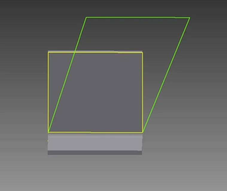
1- ask the question by an example. I have to build a folded sheet protection for an existing machine. the plan in which I will have to support the protection is not at 180° but is inclined to 122°. when I start a sheet metal part and choose a plan to draw my sketch I am obliged to choose x y z. can not choose a different plane, tilted by x degrees? or, without creating a plan at the beginning, could I draw all my piece on any plane and finally tilt it (roll it) of the necessary degrees? I didn't find the command. exists only in sketch but it is not what I seek. to better understand, observing the image below, what should I do to move the smaller flange (and consequently all the rest) on a plane that is not what I designed?

2- When I use the flange command to create a new fold, the command creates a straight flange compared to the selected edge. and if you want to create it oblique and then bend it into the press folds off team? In the example below I traced the hypothetical green lines to understand the example of what kind of flange I would like to create.
Esempio 2.webpThank you and good night.
 
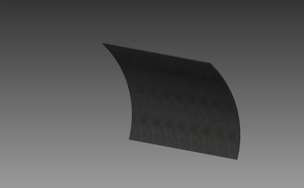
Here I am again. Following the indications found on a discussion here in the forum (which I no longer find) I am trying to make a shovel as in the image below reported.
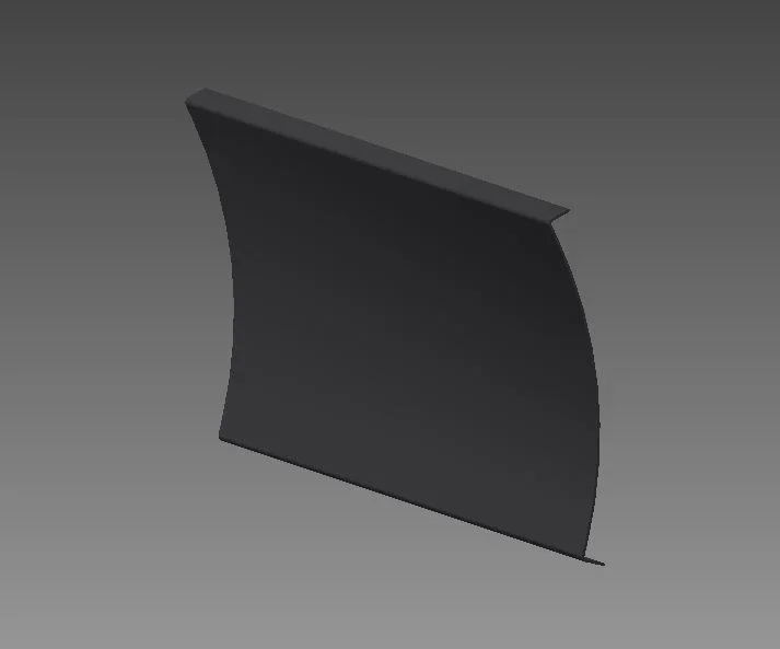
Lama.webpfrom the sheet / sketch environment I performed a simple arc not closed. Then I used the flange control out. But I don't know if it's the right way to proceed because now I should create two simple 90° reinforcement flanges above and below the sheet. However, by performing the flange command not "free" the edges and does not allow me to create them.

I am attending an inventor course, but apparently the sheet metal environment (which was the most interesting thing to me) we will study it marginally. would you then advise me how to proceed?
 
if by above and below you mean on straight edges, you can do it by extruding the straight thickness of the beam size fold + 0.5mm and then make a flange on that extruded part. But then look at the development because you will have to use the table method folds because you have the k factor for the calandra which is 0.5 and the one for the fold that will be what you feel most correct (this is an infinite story....).
If you want to create flanges on the curved edges you can't do it, or you can do it by ingeniously, but then it doesn't develop.
 
very kind.

That's what I mean. :finger: now I'm curious to try. :wink: then in fact I will have to realize also of the side banks that will have the same radiation of the shovel. I'll make them apart and then weld them by the side. knowing the beam of the folded sheet (which obviously in reality will not be as it should be) I should not have trouble making them.

In practice it is a kind of snow shovel, so much to understand and I wanted to try to create it from 0 with inventor.

However, the more I bend into the environment, the more I understand how complicated it is. and not always everything seems to have a solution. Sometimes I want to bang my head on the monitor. Now I try, then I put an image of the result.
 
Done...
Lama.webpThat's exactly what I wanted to do. Thank you 1000. is it from private lessons for inventor? :cool:
 

Forum statistics

Threads
44,997
Messages
339,767
Members
4
Latest member
ibt

Members online

No members online now.
Back
Top