Pigowallace
Guest
Hello everyone,
hoping I'm not wrong section, I'm here to ask for help on the electric environment of ansys. I will try to be concise and as clear as possible in exposing my problem.
I have to optimize a model for studying the propagation of a clique from a hole through the dcpd method (direct current potential drop). At the moment I designed and lightened a model using the passing symmetry plan for the hole. so doing I have half plate on which I can work and give constraints, but I also have in view the plan along which the clique develops.
I shaped the clique as a faceplit of the symmetry plane because, given the reduced thickness of the plate, I have a two-dimensional advancement.
Now, my question is this.
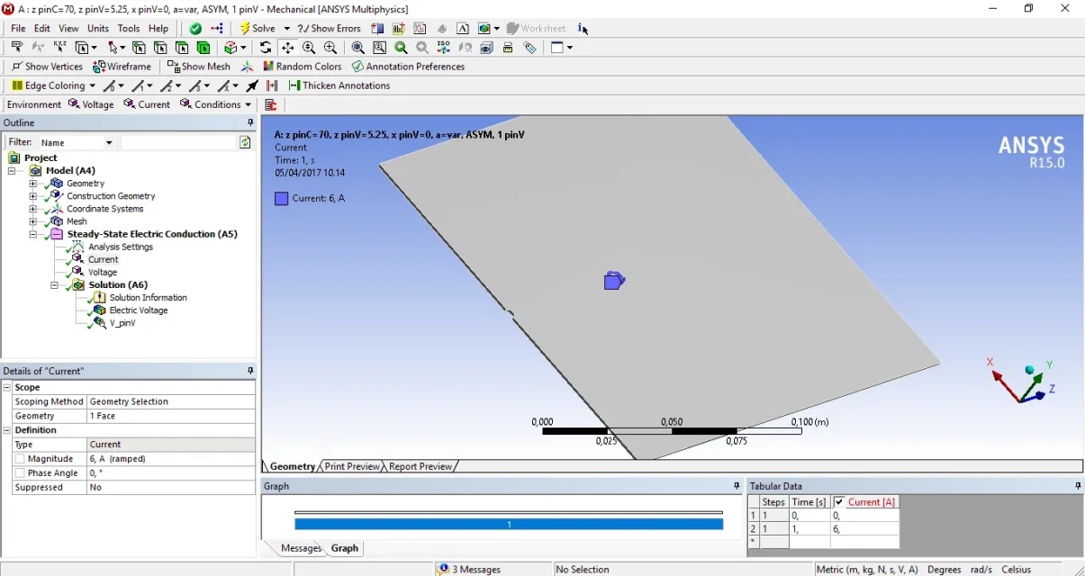
the real model consists of two (or four) probes for the voltage detection in as many points and two cables for the input of current to 6a.
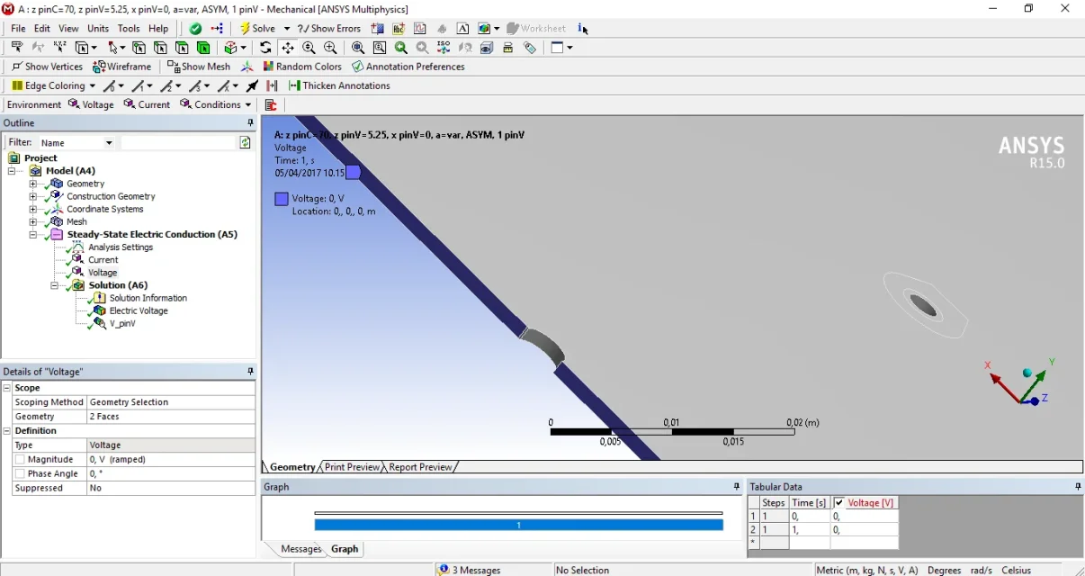
working on the semi-model in ansys, I gave only one outlet point and then, on the symmetry plane, I gave v=0. this because I did not find other ways to get the calculation of the voltage field.
Is there a more refined way, perhaps using symmetry commands or anything, to model everything? because it seems strange enough to give v=0 on that surface, but maybe I'm mistaken because I'm not in the electrical field and above all little ironed on ansys electric.
As for the current instead, if you want to switch to a complete model, how do I give an input and an output?
and always about the complete model (a plate with a hole in the center), do you have any idea how I could shape the two-dimensional clique that in the semi-model I defined as a faceplit?
I know that it's all unclear, but in case I'm open to explanations and clarifications.
Attached I put two screenshots of the model hoping it can help make clarity. in one you see the whole plate with the constraint on the current, while in the other I have enlarged on the hole so that it is visible to the solution adopted in that area.
Thank you very much in advance for your help.


