• This forum is the machine-generated translation of www.cad3d.it/forum1 - the Italian design community. Several terms are not translated correctly.

motor vehicle verification

babu50

Guest
Good morning to all, I found myself on this forum and would like to ask a question.
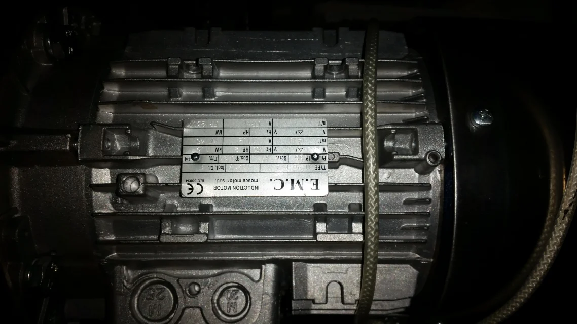
currently to move a load between my house plans I use a modest hoist with 800kg rope of 10 mt in fabric (type car seat belts). It works fine but makes noise and then decide to request a winch. I propose a gearmotor formed by gearbox size 90 with ratio 1/50 , slow shaft output on which I made the drum of 32mm diameter and motor autofrenating 4 poles 220v monophase 1.5kw. All on a frame, I wrap the 10 mt band on the drum and at this point the diameter from the shaft passes from 32 mm to 150 mm. I do the empty evidence and am fully satisfied with the purchase is very silent. I take everything in the attic and replace the hoist with the new harpen, unroll the band up to the ground floor and hang a load of about 250 kg. begins to rise but known that the brightness of the lamp in the attic decreases considerably and the engines after about 2,5 mt of lifting stops and can no longer restart. I require an increase in power to enel from 3 to 4.5 kw, I get it in very short time. I try to restart the engine but the result does not change. Now the only thing I can do is to put an additional capacitor to increase the boot couple that I will then disengage through timer, but I am titubante because in my opinion it wronged the calculation the supplier of the motor. the thing leaves me stupefied as the engine of the hoist I have used until now is 1hp, advice? a huge greeting to all
 
a motor without adjustment of turns placed under load with 1,5kw can give problems of electricity grid disorder. If it is monophase with the condenser you can have some improvements at the point but obviously you have to do two accounts on the supplied pair.
you have to calculate the pair to the drum... .
1.5kw-1500rpm are at the reducer with i=50 470nm and if the drum is 32mm ...son about 304kg lifting.
There's something wrong with the adjustment.
 
Thanks mechanicalmg for the prompt response, but unfortunately you speak with an electrotechnic that never had to make calculations like that, from what I understood with 50 turns/min I have 470 nm with drum 32 mm, but if the drum increases to 150 mm due to the overlap of the edges of the band to how many kg the lifting is not able to calculate it. last thing keeping the self-frenating motor which is the most sustained cost, what reduction ratio on the gearbox should have to be able to use it to my purpose and how many kg I can apply. thanks for the courteous answer
 
470/150*32=100nm = 10kgm ( 10 kg to 1 m radius)

with diam. 32 lifts ( 10* 1000 / (32/2 ) = 625 kg )
with diam. 150 lifts ( 10* 1000 / ( 150/2 ) = 133 kg )

when 80 in diameter the gear motor doesn't make it anymore and... the light turns out.
 
hi stefanobruno for the courteous answer, but now I have a question to ask you, reducing the reduction ratio from 1/50 to 1/80 and decreasing the diameter of the drum wrapped from 150 to 120 making the appropriate calculations (using the proportions and not the specific calculations) turns out to me that I can lift more than 300 kg, of course with less speed, but using the 1.5kw engine replacing the only reducer, than the a big thank you marco
 
who sold you the engine and the gearbox I think it's a cellarer because he didn't give you what you need. sure that even you... if you are an electronic and not an electrician, look at the engine tag and you will find the torque rated engine. if the multiply for the reduction ratio (50) get the torque in n*m to the reducer. If the pair is strength by arm... ..and by itself that force equal torque divided arm. the pair is in n*m and the arm is the drum divided two....in meters. So find the strength in newton... ..that you divide for 9,81 and get the pounds you lift.

We also have electronics starting sophisticated systems that have problems in elementary formulas. ...too much is the mediocrity of the technicians....then the evolved ones cost to the companies....
I thank you mechanicalmg, but as I told you my work was quite different from the question I asked you, if it was my "pane" I wouldn't have bothered you don't think? I think you don't have exactly what a plate of a motor says, but the data you mention I don't know where you took them and I attach photos of the engine plate (discussed but the image is flipped and I don't know how it. However I thank you for the courtesy shown me, effetently those who sold me the whole has definitely wrong in the design but he was an engineer, at least so he told me and we will see if I can conclude the project since they promised to contact me and I wanted to have some extra data and that is why I asked help to this forum that I warmly thank.marco
 

Attachments

  • 20180128_230036 - Copia.webp
    20180128_230036 - Copia.webp
    997.5 KB · Views: 23
the data I mentioned unfortunately are not on your tag, but if you find a catalog or if you do two accounts on the flight you know the torque provided by the engine using simply number of turns and power.
then the reducer will have a plate with reduction ratio. If you are looking for its catalog you can see the performance and understand how much torque is available to the tree and then get the power generated by the winch.
from the phone I don't see the displacement of numbers though you write:
- 4 poles = as such makes 1500rpm nominal. ... running no more than 10%....effective will make 1460rpm
- 1.5kw = the power is that

the nominal torque of the engine is worth cm=wm•1000/(2•3,14•n/60)=9,8nm
the torque is cr=cm•return•i= 9,8•0,8•50=392nm
force in kg liftable according to dtamburo e f=cr/(0,5•dr/1000) with dr in mm

Keep in mind that your engine could give a point torque between 1.5 and 2.5 the nominal torque.
 
hi mechanicalmg, just contacted me the engineer of the company that sold me the motor group and confirmed that their calculations are accurate and that perhaps the fact that the motor stops after having traveled about 2 meters (with a load of 400kg) is for the intervention of the brake and not because insufficient the motor group, told me to try to uninsert it and I will certainly see that it raises the 400kg. I can do this to confirm or not his hypothesis
 
actually is the brake that causes the problem, in fact excluding the engine has no problem, I think at this point to make a change, at the start do voltage to the brake and then after about 0.2 seconds to the motor all through timer.
 
did the electrofreno require it to have more precision in the hoisting (stop faster) or for safety reasons? if the reducer is of the screw type without end and crown ( rather probable for a high relationship like the one indicated by her) take into account that, with i = 50 as in his case, it is irreversible, then the load applied to the pulley fails to make it turn "on the contrary" . if the electrofreno has the release lever (in the photo you do not see) can release it quietly, it will see that the load that is lifting will not return.
if instead they provided a gearbox with parallel shafts or conical pairs, the load must hold it with the electrophrene, but it was not the best choice for a "artisanal" hoist
 
the reducer is of the screw type without end. at this point the only thing to do is to try by putting in place the change of power separately motor and brake, first feeding the brake and then after 0.3-0,5 seconds the engine
 
I did what I wrote in the previous message and added a second capacitor in parallel to the existing that after about 20 seconds I exclude through timer, but the result is not substantially changed, the supplier tells me that the reducer and the engine are suitable, in fact if part with the drum played manages to climb up to the top but if I stop it in an intermediate point there is no way to make it restart. I accept advice, I greet you and apologize for the trouble. Mar
 

Forum statistics

Threads
44,997
Messages
339,767
Members
4
Latest member
ibt

Members online

No members online now.
Back
Top