• This forum is the machine-generated translation of www.cad3d.it/forum1 - the Italian design community. Several terms are not translated correctly.

mounting and clamping bearings

Parzival

Guest
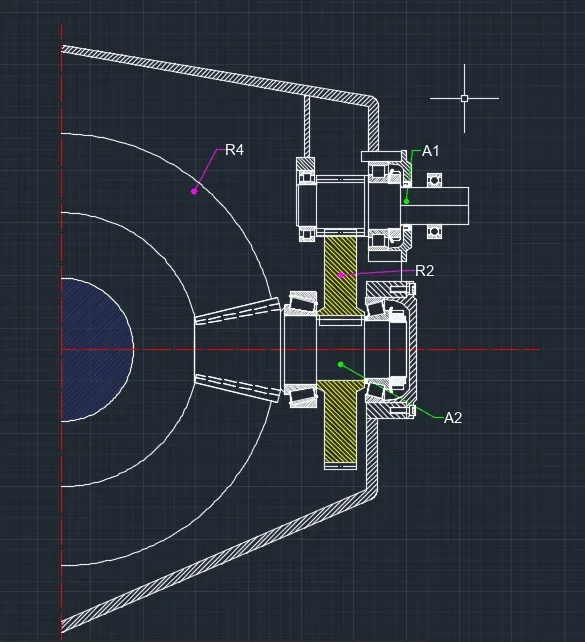
Hello, I am a new user, I would need your help to know if my bearing design of my gearbox is done well. I had designed the bearings so that the one above is a hinge and the one below a cart, but I'm not sure that I mounted them in the right way. Could you give me some advice or maybe some files to visit? In the meantime, I attach an image of the trees concerned. Immagine 2020-12-28 171433.webp
 
the green toothed wheel (left) touches both the inner ring and the outer ring of the bearing, preventing the relative rotation. the other bearing instead does not form the constraint of cart.

Central wheel: you put two cylindrical roller bearings: They are equal to two trolleys. labile structure

the r2 wheel (yellow) with who ingrains? Moreover, conical roller bearings have the inner wheel that rotates at the same speed as the exterior.

Finally there is the third tree from the left: Conical roller bearings are only stuck in the two diagonally opposite points. up there is a seeger too. the lower bearing is fine
 
I don't see any pins in the holes to stop the outer ring bearings.
spacers must be processed and not paper sheets (white thickness under green wheel).
the slow axis has the bearings with floating mounting (see other discussions on bearing mounting)...so there is no hinge and cart.
there must be more space between the walls of the carcass and the sides of the gears.
sure that heat dissipates heat?
 
Parzival, think you're in front of your teachers and explain the solutions you adopted. Maybe trying to describe them you notice details that in the drawing you had escaped.
we also have your point of view that we can discuss, correct, broaden
 
Schermata 2020-12-29 alle 10.33.41.webpwheel 2 (it would be the yellow one I modified it so, I think it could be okay, I changed the bearings by putting even a conical spacing.
Moreover the request was to close with a case without having to make calculations on heat dissipation or other but only to close so that everything can enter and with the plugs that block the right things and at the right point.
the request was to insert the bearings where one is as a hinge and the other as a cart, so I looked for the shaft 3 (the vertical one with the conical wheel) to block the bearing above from all four sides putting a ring seeger and leaving under the bearing only stuck in two points so that it is considered a cart.
the same thought I repeated it for the bearings placed at the beginning of the tree (inteso come cerniere) and for those below (as trolleys).
how can I change the bearing above the 5 tree (the one with the green wheel) so that it is a zipper and effectively removing the spacer defined as "a paper leaflet" (I absolutely agree with this statement)
thank you and I hope you have understood
 
p.s. regarding the tree 1, the one above the last photo the last bearing must be left so free while others should be mounted in the right way
 
I have the impression that they lack sampling; It is not clear where the carcass of the reducer ends and where there is the vacuum. it is difficult to understand the installation.
I would also remove the teeth of the central and right gears that weigh the design, do not serve anything and make the transmission uncomplicated; to have a common language I would point out the main elements, as you really do in drawings, discussion (shaft a, bearing a1 and a2...) so as to avoid long descriptions to indicate what you are talking about (the upper bearing of the tree to the left = a2).
various comments:
fange does not need to do inclined internal digging while also reducing contact with the outer ring of bearings. look in the manuals of the skf the minimum and maximum size of support.
left tree lacking lines on the definition of the wreath
left shaft the diameter of the wheel should have a diameter greater than that of the bearing for not having to mount to interference a section not necessary
lower shaft flange on the left, the seal is not blocked
lower central shaft wheel can move upward
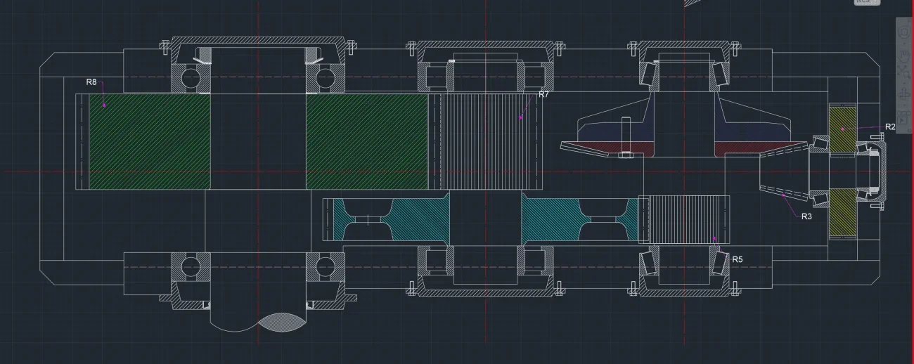
 
shaft 1 is mounted on two cylindrical roller bearings: labile because trolley.
shaft bearings 2 are not blocked: the Iberian parades to the left. right cmq locking is wrong
 
to block the bearings of the tree with the green wheel you can put "bicchieri", or create laughter in the carcass itself.
Are you a student or a university?
 
I am a polytechnic student but I come from classic and honestly it is the first time I design. in the slides that provided us the professor is said to make a difference in the mounting of the bearings if "as a hinge" and "as a cart". that's why I asked for help to you, since slides said that in mounting as a hinge the bearing had to be blocked by all four points, while only two for mounting as a trolley. and it is also for this reason that in all the bearings above the vertical trees (all three) I stuck them then with elastic rings
 
shaft 1 is mounted on two cylindrical roller bearings: labile because trolley.
shaft bearings 2 are not blocked: the Iberian parades to the left. right cmq locking is wrong
how do I do for one of two cylindrical roller bearings make it become zipper?
same question for tree 2, how do I block them? elastic or spacer rings?
 
the diameter of the bearing cannot change you just need to slightly increase the diameter of the wheel. Just a little, even just 1/2mm.
this assuming that the wheel is mounted to interference.
 
Okay, so changing the diameter of the wheel then I would go to put the bearing on the shoulder that would grow, right?
As for tree 4 instead, I should make another shoulder between wheel 6 (the celestial one) and wheel 7 (the one above), so that you can't move, right?
 
Okay, so changing the diameter of the wheel then I would go to put the bearing on the shoulder that would grow, right?
exact, so you would avoid the paper sheet already reported by mechanicalmg.
a coupling with wheel interference implies that there will be no axial shift of the same and therefore if between wheel and bearing there is some millimeter of light is not a problem; also you would have contact only with the inner ring of the bearing
As for tree 4 instead, I should make another shoulder between wheel 6 (the celestial one) and wheel 7 (the one above), so that you can't move, right?
wheel 7 is integral to the tree, otherwise it was dissected, so the shouldering already has it
 
you would have contact only with the inner ring of the bearing
Thank you very much
instead I would have a question about the bearings that are above these three central trees, because they are those that I would like to mount as "cerniere" and that's why I put elastic rings, but apparently they weren't okay, what could I do?
 
how do I do for one of two cylindrical roller bearings make it become zipper?
same question for tree 2, how do I block them? elastic or spacer rings?
the zipper is made with ball bearings. to remove one of the two bearings and replace it with a ball bearing stuck in 4 points.
the cart instead is made with cylindrical roller bearing stuck only in two points.
the two points are chosen on the same ring: or lock the inner ring in two points or lock the outer ring in two points. Hybrid solutions do not work
 

Forum statistics

Threads
44,997
Messages
339,767
Members
4
Latest member
ibt

Members online

No members online now.
Back
Top