boraborazz
Guest
hi to everyone, from a few days I've been trying to solve a problem using patran-nastran but I don't understand how to do it.
the problem is just this: strength ratio in a random patran-nastran analysis. are at the basic level therefore I ask you forgiveness for any banality.
I did a random analysis using composite materials and got the various accelerations of rms, given a certain input psd.
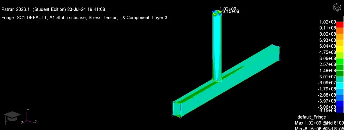
My problem is to find the maximum tensions: in patran random analysis gives the possibility to get and display stress, but not for the various layers of the composite, but only for z1/z2. I would like to get stress for each layer, so I thought I would do a static analysis but I can't figure out how to do it: I thought I would apply the accelerations resulting from random analysis on a static model, but how should I do it? the bond conditions remain the same as the random analysis (i.e. 23456 at the base, leaving free x) or do I have to bind differently?
In this case I thought of applying the resulting accelerations, but perhaps I could apply the movements resulting from random analysis if you think it is easier.
I thought about the accelerations because in the .bdf is present the command param,nocomps,-1 and I do not want the movements to be calculated from the stresses (in doubt I used the accelerations).
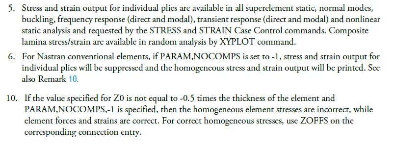
in the quick reference guide of nastran I found some remarks useful to evaluate the tensions that I attach, although I must say I have not understood well with "composite lamina stress/strain are available in random analysis by xyplot command."
n.b: obviously if you change the command to param,nocomps,1 you could get stress for the various layers of composite, but in this case it is not possible to apply the input psd to finalize the random analysis, so it is not possible to do this.


