• This forum is the machine-generated translation of www.cad3d.it/forum1 - the Italian design community. Several terms are not translated correctly.

possible error in the reaction force due to the simulation of contact between two bodies

Lillo86

Guest
Hello everyone,
I would like to ask you a possible problem in the contact study between two bodies. In particular, it would be a mistake on the calculation of the reaction force due to contact between the two bodies concerned.

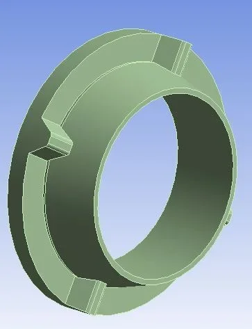
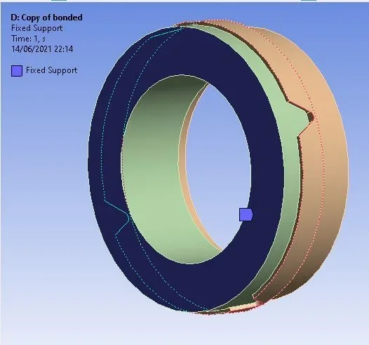
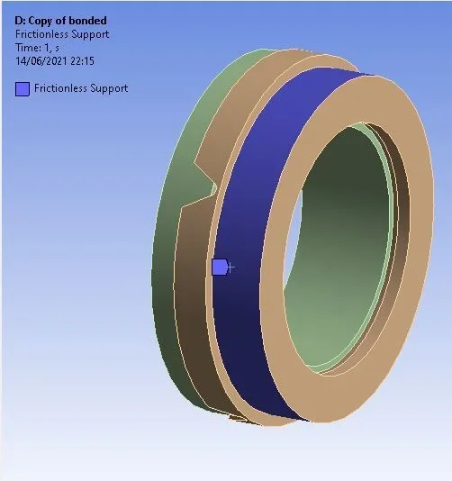
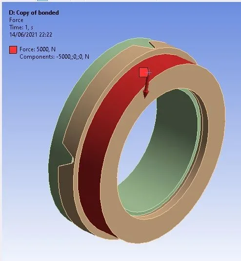
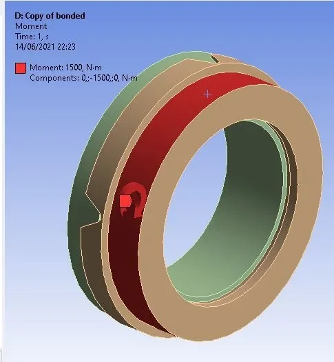
as seen from the figures I have a "pink" and a flange that mate with each other through different conical surfaces. at the end of the pin there is a fixed support, while at the end of the flange there is a concentrated force and a concentrated moment that simulate the weight effect of a tree that is mounted on the flange and whose center is eccentric compared to the center of rotation. this tree is supported at the two ends by two "perno-flangia" couplings (however in the simulation I considered one pin, halving the weight of the mass to support, so as to simplify the model).

the contact bond has been assigned as follows:

- contact type = frictional

- pin = contact

- flange = target

- friction coefficient = 0.7 (steel vs steel)

- behaviour = symmetric

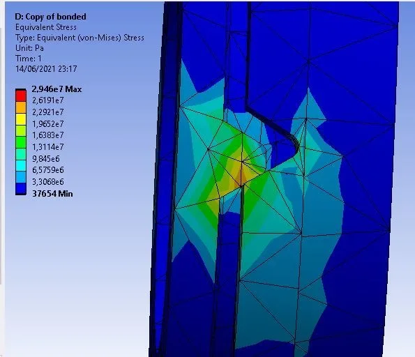
However, going to solve the model, I noticed a possible inconsistency. the total reaction of the moment evaluated to the fixed support is 1500 nm, exactly as the moment I applied to the flange; But the total reaction force is much lower than the 5000 n applied by me. what could be the reason for this discrepancy?

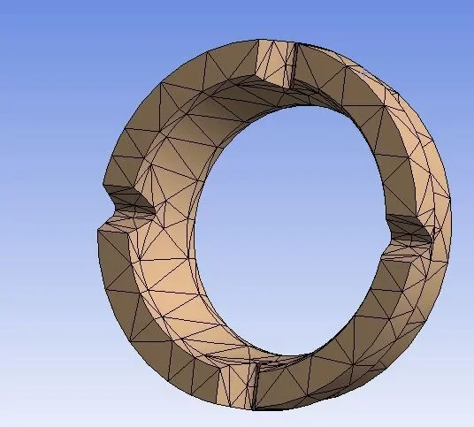
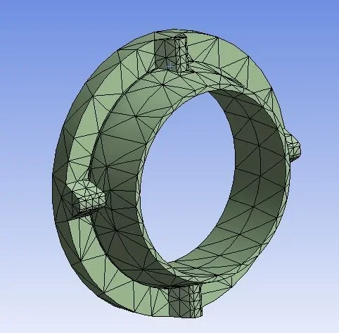
I would also like to ask you if you think it is appropriate to improve mesh and, if so, what strategy could I take to achieve the purpose
 

Attachments

  • 2.webp
    2.webp
    13.5 KB · Views: 6
  • 3.webp
    3.webp
    10.3 KB · Views: 6
  • 4.webp
    4.webp
    24.1 KB · Views: 6
  • 5.webp
    5.webp
    20.5 KB · Views: 6
  • 6.webp
    6.webp
    22.9 KB · Views: 6
  • 7.webp
    7.webp
    23.4 KB · Views: 6
  • 8.webp
    8.webp
    17.2 KB · Views: 6
  • 9.webp
    9.webp
    32.4 KB · Views: 6
  • 10.webp
    10.webp
    33.6 KB · Views: 8
  • 11.webp
    11.webp
    34.4 KB · Views: 8
As for the history of loading I did not understand how you applied forces and constraints....but if the two flanges have radial force application and torque moment can not have the same load because the horizontal notches see on one side the sum and on the other the subtraction of the two effects.
the mesh definitely is not good because in the conical pens you have to have at least 3 elements. the general mesh is big, it must however be made smaller and intensified in the contact zones.
 
I can tell you that I have a model placed under analysis where I have a frame-shaped carpentry, loaded inside with forces due to hydraulic cylinders that led to the evaluation with foundation tirants and therefore with the contact reaction with the floor as follows:
- Simulation with contact ansys and tie rods: +50% error compared to reality
- Simulation with solidworks contact and dyes: +30% error compared to reality
- Simulation with solidworks reversal without contact: +18% error
- simulation with freecad workbench fem based on calculux, static linear and non-linear, reversed application without contact floor: error of +15% compared to reality
- test in workshop with comparisons: real condition

all simulations have overestimated the behavior of the deformations of much, and the more the analysis is accompanied by more things (contact, friction, tie) and the more the error rises.
 
Hello! Thank you very much for the answer!
As for the history of loading I did not understand how you applied forces and constraints....but if the two flanges have radial force application and torque moment can not have the same load because the horizontal notches see on one side the sum and on the other the subtraction of the two effects.
the mesh definitely is not good because in the conical pens you have to have at least 3 elements. the general mesh is big, it must however be made smaller and intensified in the contact zones.
Yes, I actually made a modeling mistake. in the sense that in an attempt not to create a swing beam I have bound the flange with a frictionless support that then goes to completely cancel (or almost) the effect of the applied loads. I solved by adding a beam element to the middle of the flange that simulates the effect of the beam in a more realistic way.
I still have a few issues about shaping contacts, but I think there's a mesh fact.
I can tell you that I have a model placed under analysis where I have a frame-shaped carpentry, loaded inside with forces due to hydraulic cylinders that led to the evaluation with foundation tirants and therefore with the contact reaction with the floor as follows:
- Simulation with contact ansys and tie rods: +50% error compared to reality
- Simulation with solidworks contact and dyes: +30% error compared to reality
- Simulation with solidworks reversal without contact: +18% error
- simulation with freecad workbench fem based on calculux, static linear and non-linear, reversed application without contact floor: error of +15% compared to reality
- test in workshop with comparisons: real condition

all simulations have overestimated the behavior of the deformations of much, and the more the analysis is accompanied by more things (contact, friction, tie) and the more the error rises.
In fact, to know that simulations tend to overestimate tensions and deformations of the material, I regret a lot. At least I know that the real system certainly does not yield.
an underestimation would have been much more worrying
 

Forum statistics

Threads
44,997
Messages
339,767
Members
4
Latest member
ibt

Members online

No members online now.
Back
Top