• This forum is the machine-generated translation of www.cad3d.it/forum1 - the Italian design community. Several terms are not translated correctly.

practical advice creation of large assemblies.

  • Thread starter Thread starter New Rider
  • Start date Start date

New Rider

Guest
Good evening,

I've been working on large axioms lately, or rather assimilate with different components installed.
I would like to know if there are tricks/consistencies to create these types of assemblies.
Specifically, to better understand, you have to make a machine long hypothetically 10 meters. these 10 meters of automation divided them by type of processing (e.g. material input, processing 1 , processing 2, processing 3 and finally expulsion of the piece ).
instinctively I will create many assemblies " macro " how many processing (in the case just described are 5 ) that my stain will have to go to perform. of course every " macro" assembly will have all the necessary components for its "mansion". I wanted to understand how to proceed. Is it better to work by inserting in the macro each part or I should be able to escape even more by inserting in the "macro" set of the sub-axis?
example as from photo attached :macchinaperpasta_STA400_1.webpI have all this machine that will be connected to another machine for continuous machining of the piece. to divide (as already explained before.. ) I will create macro assemblies.
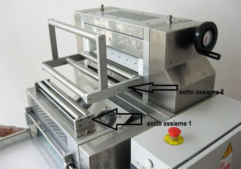
to create axiemi macro it is better to insert, I repeat every single part (rolls,cuscinetti,segger,viteria etc.) or to create sub assemblies also of some components as pictured? what advantages/disadvantages would bring me this type of work?
I hope I've been clear.

cordially.
 
You don't have to put all the parts in every "macro", absolutely!
you have to continue with the same philosophy, you have to create so many assemblies as are the processing phases, a firm set, a set
etc. etc.
For example, the photo seems correct to me, you will also have a framework set that will contain carpentry (the sheet that you will then paint) a set where you insert the connectors and the safety button (you don't put them first if you don't paint them), together electrical components etc.
returning to the photo if for example the subaxieme 2 is made from 2 parts (flat rollers and rollers in vercale) do 2 more subaxiemi and if each reel is made from two parts, you will make another under one together roller.
so I do and I find myself well, of course sometimes you avoid doing some together, but the rule is above.
Then I give you another advice, be very careful when you assemble everything, if you tie very much geometries, you risk creating paper castles, you fall a piece and you fall all. we were a skeleton that contained sketches and plans and served to mate the assemblies.
 
axiemi, subassiemi, axiemi cin speedpack or a defeauture of each machine to be reassembled all in a total set
 
Hi.
we make rather large assemblies (150000corpi), composed of many parts and some of these parts have quite complex geometries (cast iron castings). we try to create more possible subaxis (called assembly assemblies, because they are combinations of details that can be mounted at the counter, before being mounted on the machine).
for each assembly we create the configuration in which everything is mounted and a configuration in which we suspend all the non fundamental components (such as screws, or), for castings we make the configuration with bevels and fittings, and the one without...
the purpose is therefore to display the right detail for the level of interest.
It is useless to view/load the bombed screw that supports the internal cooling fan in the general axieme of the machine that you will use for the customer's lay-out.
our rule is therefore: the right detail at the right level.
this philosophy generates a small error on the overall masses, but it is normally negligible.
In your specific case, I would tell you that all the laminated and vased screws that you have assembled must be loaded into the axieme of which they are part, but when you use that axieme in a father set, I would suspend them. (unless you need complete distinction).
There is no general rule. ..where you find the road best suited to your needs
 
Hello,
even I like you at first had these problems in fact if you are looking for 2 my conversations even with a moderate number of answers.
I totally agree with that said above. However, a further problem could be to see the movement between one and another. solidworks calls for less flexible subaxis possible.
for this I recommend you also create configurations of the movement that can have a subaxieme (for example a lever a maximum point and one at the minimum point and maybe a third where the component is free to move so that you can check the movement). therefore take into account this aspect when I can guarantee you to be fundamental. in my project I did not know and I created the various groups without configurations. I'll just let you imagine.... you couldn't see a position of the failing system crying.

defeature is important. for the configuration of the screws depends also on what solidworks you have... with the standard version you have already solved the problem because the toolbox is not present.
if you have the premium and you will also have to do dynamic analysis or fem you don't know how to give other advice about subdivision of such subaxis and configurations. would be a good argument to be dealt with anyway. . .
mechanicalmg (and perhaps kakisan) I know that it is quite armed on such points:wink:; Surely they can help you more.
 
right... flexible help me. . .
use them less than you can. ..why remember that maybe you need only 1 free gdl, but he frees all those missing in the subaxieme,
means that each screw will be free to rotate on its axieme if the axieme becomes flexible.
 
the important thing is to focus your plant well.
for example ours are plants from 5 to 8 axes and we have a lot of groups enlivened by different cams but from the same tree.
each group has its own cam and then in the macro axieme I commanded the tree by table that manages the degrees of the engine. each cam is bound to the halfway plan of the tree. when changing the engine grades the cams rotate and therefore also the groups. sin that mating cam is not very stable and sometimes from some problem... .
 
I'm crying. . .
Thanks for the advice... to tell me that the components that stand (e.g. bearing/bearing rather than pulley/segger) I insert them as under axiemi. the things that have to be installed individually in the assieme I leave them as parts. This should help me in the explosions (other roar than for the avoided moment) going to create me for every single under his explosion and relative putting into the table.
depends on how you organize the project. But after a couple of asses you'll see that you'll get a clear idea... I had the problem of flexible subaxis mainly with the tire (actuators etc.) I solved as I mentioned above (for this I can thank kakisan :redface: )...
 
I can only say that the projects have already been made by other operators previously. I am, for example, with macro assemblies that have the reference plans of the fixed component completely opposed to the reference plans of the assembly.
 
I can only say that the projects have already been made by other operators previously. I am, for example, with macro assemblies that have the reference plans of the fixed component completely opposed to the reference plans of the assembly.
Unfortunately dementia, menefreghismo and lack of specific skills causes a series of cascading problems. I would propose the elimination of the subjects with a nice extruded cut:) I clash every day with these things....
 
a flexible assembly is a set that, once loaded into a parent set, allows to free the missing constraints in the child's assine and perform free movements.
For example, the cylinder +stelo axieme, in which it is left free handling along the cylinder axis, when it is made flexible in the axieme in which it is loaded, allows the handling of the stem.View attachment CILINDRO.zipin the axieme that I attach you (along with father) you will find 2 configurations:
flexible . where the cylinder underarm is flexible, then the stem moves
not flexible: where the cylinder subaxis is fixed and you cannot move it.
I hope I helped you.
 
I can only say that the projects have already been made by other operators previously. I am, for example, with macro assemblies that have the reference plans of the fixed component completely opposed to the reference plans of the assembly.
as stylistically an heresy, it is not a huge problem.
it would be nice to have every fixed part, bound on its origin and origin of the axieme in which it is mounted (I am rather dotted on this factor), but not always unfortunately the other people work neatly.
it is necessary to make him understand that an orderly and intelligent design to long go reduces work and increases productivity.
At this point it is up to you to work well and catechize others... but with someone it will be a lost cause.
 
I'm crying. . .
Thanks for the advice... to tell me that the components that stand (e.g. bearing/bearing rather than pulley/segger) I insert them as under axiemi. the things that have to be installed individually in the assieme I leave them as parts. This should help me in the explosions (other roar than for the avoided moment) going to create me for every single under his explosion and relative putting into the table.
there is no general rule,
You should understand what you want to do.
definitely create and manage a subset composed of pulleys+cuscinetti is probably a waste, especially if it becomes an encoded set managed by the erp (modifications, drawings, distinct... )
However, it depends on the type of product you have.
 
as stylistically an heresy, it is not a huge problem.
it would be nice to have every fixed part, bound on its origin and origin of the axieme in which it is mounted (I am rather dotted on this factor), but not always unfortunately the other people work neatly.
it is necessary to make him understand that an orderly and intelligent design to long go reduces work and increases productivity.
At this point it is up to you to work well and catechize others... but with someone it will be a lost cause.
Sorry but I didn't understand!!!! it is not polemical you mean I just want to understand.... seen that I use solid for about 8 years but always alone!!! I never had the pleasure of comparing myself to work with others so I could realize that I was wrong all until now.
then I try to be as tidy as possible in design but my order consists of this:
I give references from the plans of the assieme ie the parts are bound to the plans of the main axieme with consistency "when this is possible" (right plan with right sup with sup and so on). but I have never used the origins you can tell me whether this is right or not and then how the system works with the origins in the sense that a origin does not bind the part you have to give it another reference

Thank you.
 
Well...theseo, I'd say yours is a different way to get to a good result.
I use the origins on the fixed component because I use very much geometries to bind the parts (and very little references).
I amount together the first part (which will be the fixed one) making sure that the origin of the part coincides with the origin of the aid. Then I put the other parts on the first part. ..because I have the luck that each part has a real mechanical coupling with the part on which / with which it binds!
if instead for various needs this is not so, I use plans or sketches of layout.
 
However the most important thing is to be very ordered and always follow the same road.. .
But then you're all about plans? Don't you use faces?
what products projects?
 
no I also use faces; but everything starts from the plans or better if I can first use the plans then the faces or points etc.
- - - updated - - - -assembling and automation machines in general.... .
 

Forum statistics

Threads
44,997
Messages
339,767
Members
4
Latest member
ibt

Members online

No members online now.
Back
Top