alexrib89
Guest
Good morning to all,
It has long been that I have been registered in this forum so I believe (but I'm not sure) that I was introduced years ago! :wink:
I read a lot of your discussions and often find answers to my questions.
I have graduated in mechanical ing for just over a year and currently work in a small and young company that realizes test benches. my task (besides other marginal tasks) is to design and draw frames in carpentry and machined parts
This time I am here to ask you a question, which if marginal, has created several disputes between me and my colleagues in the design office.
I predict that my experience in this sector is not very developed, given also age, but I am a pointy, attentive and passionate type, so I grew up quite quickly in this job role (although I still have a lot to learn).
after this brief preamble we come to my question.
I often find myself drawing mechanical components made through the welding of sheets and then worked with milling; like others in this forum the welded axieme of inventor that allows to represent the crude, and the finite. And so far it's okay.
for the simplest pieces we avoid making the rough design, listing only the finished piece, and to facilitate the interpretation to the mechanical builders (external companies) we insert in the first page of each design the separate cut of the various elements constituent the assemblies (e.g. sheet 5 150x150).
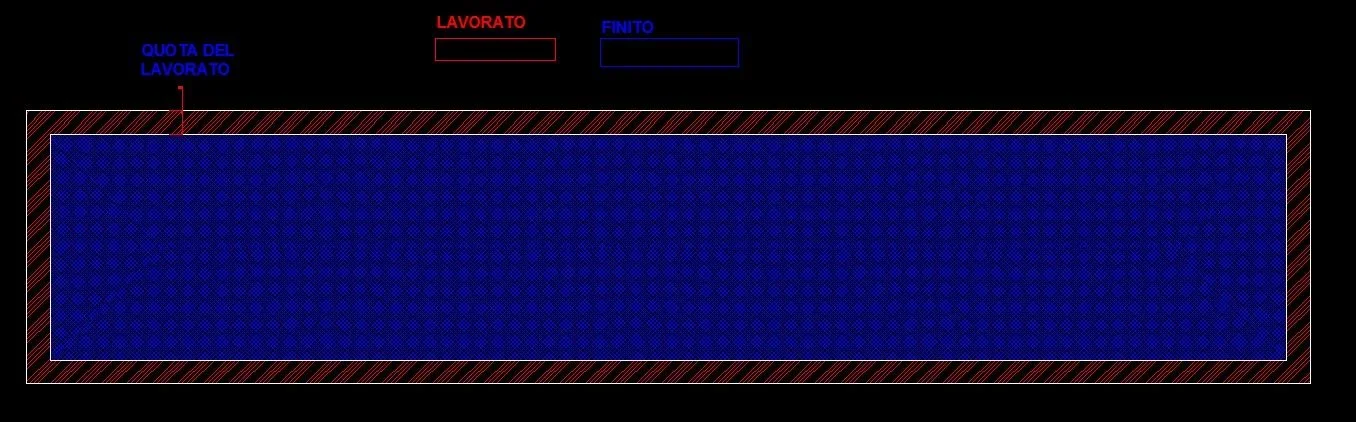
I put the measurements of the crude and on the side I insert the mm of metal over which I am estimated to be removed, I give an example:
"lam. sp. 15 150x150 including 3 mm of metal over"
then in the axieme listed the thickness of that sheet (which will be poured out of millet) will be indicated with the quota "15mm finite"
I have found in law how the metal over is quoted, but it gives me the idea that this information is not clearly received by the final operator and I do not know how well it fits with welded pieces that require the removal of material only on some faces.
Now I ask you:
according to you this method that aduced is right?
can you create confusion in the process of realization?
how do you do these things?
thanks in advance of the answers you will give and hope to have been clear!
Bye!
It has long been that I have been registered in this forum so I believe (but I'm not sure) that I was introduced years ago! :wink:
I read a lot of your discussions and often find answers to my questions.
I have graduated in mechanical ing for just over a year and currently work in a small and young company that realizes test benches. my task (besides other marginal tasks) is to design and draw frames in carpentry and machined parts
This time I am here to ask you a question, which if marginal, has created several disputes between me and my colleagues in the design office.
I predict that my experience in this sector is not very developed, given also age, but I am a pointy, attentive and passionate type, so I grew up quite quickly in this job role (although I still have a lot to learn).
after this brief preamble we come to my question.
I often find myself drawing mechanical components made through the welding of sheets and then worked with milling; like others in this forum the welded axieme of inventor that allows to represent the crude, and the finite. And so far it's okay.
for the simplest pieces we avoid making the rough design, listing only the finished piece, and to facilitate the interpretation to the mechanical builders (external companies) we insert in the first page of each design the separate cut of the various elements constituent the assemblies (e.g. sheet 5 150x150).
I put the measurements of the crude and on the side I insert the mm of metal over which I am estimated to be removed, I give an example:
"lam. sp. 15 150x150 including 3 mm of metal over"
then in the axieme listed the thickness of that sheet (which will be poured out of millet) will be indicated with the quota "15mm finite"
I have found in law how the metal over is quoted, but it gives me the idea that this information is not clearly received by the final operator and I do not know how well it fits with welded pieces that require the removal of material only on some faces.
Now I ask you:
according to you this method that aduced is right?
can you create confusion in the process of realization?
how do you do these things?
thanks in advance of the answers you will give and hope to have been clear!
Bye!