• This forum is the machine-generated translation of www.cad3d.it/forum1 - the Italian design community. Several terms are not translated correctly.

set and calculation geometric tolerances.

giusy_v

Guest
Good morning, everyone, I'm jusy and I have a little problem and I hope you can help me.
for a few years I have dealt with chains of tolerances, receiving the necessary inputs to execute the calculation.
Now I'd like to try to set geometric tolerances, but I'm not sure what I'm doing and I hope I can help.


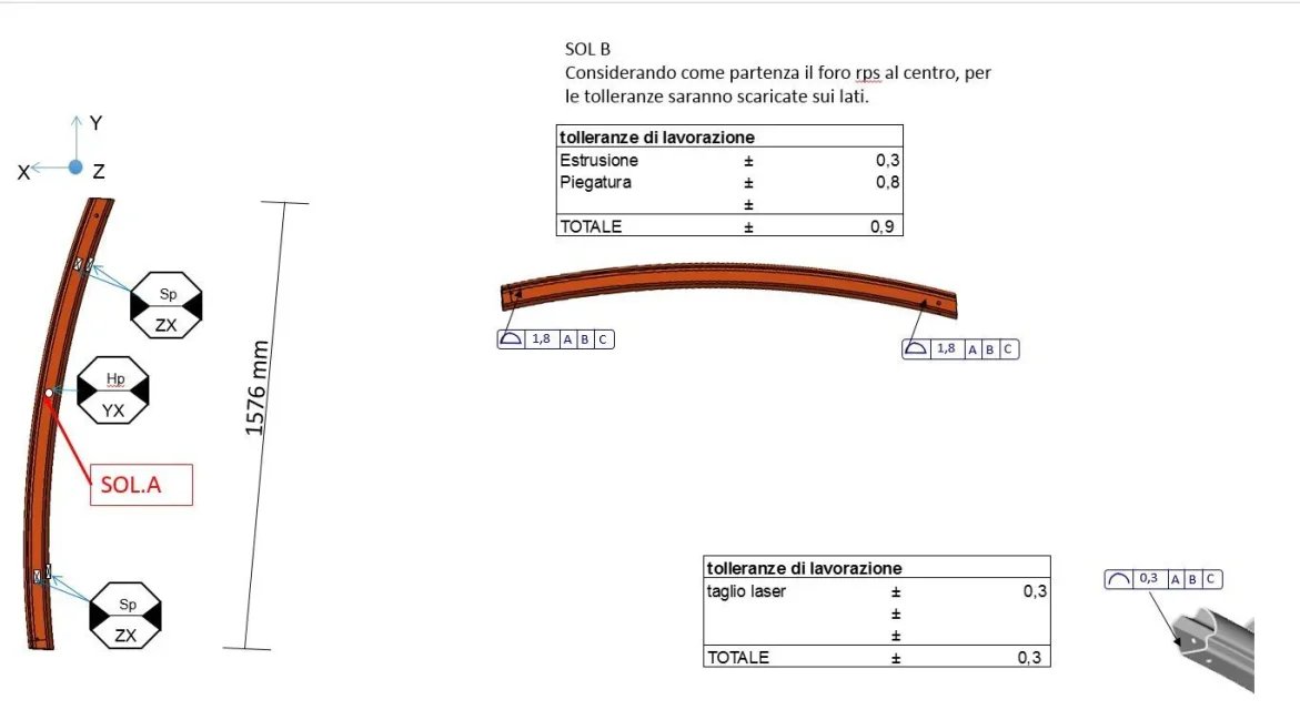
I have a steel tubular as in the attached View attachment estruso.pdf.
I thought about starting from work and considering:
Extrusion
bending
definitive cut

I neglected the others.
the extusion of a steel piece has a tolerance of +/-0.5 each m, but in this way I am not considering dimensional tolerances?
There must be something that escapes me,

thank you for anyone who can help me

Good evening
 
mmmm... in the case of geometric tolerance the criterion is to understand which is the functional purpose of the piece.
a stupid example, if you want to tolerate with geometric tolerance a bearing you should understand what the elements with which this goes into contact and what purpose it has in the axieme.
a starting point, in the case of the bearing, should be the fact that it is mounted on a tree for which the first useful reference for you is the axis of the tree: I don't know if I explained.
 
dimensional tolerances are tolerances on size numbers.
Geometric tolerances are geometric deformations or deviations of dimensions within planes or straight limits.
For example your square tube section can deform to a tot parallelgram.
 
Hello and thank you both.
My problem is that I must start from the loose element, hypothesize the processing and trace back to the geometric tolerances and then trample the axieme of which it is part.
are tubular to build a cabin of an agricultural medium, therefore mainly serve to create a structure, then to have hinges for the doors and finally the instrumentation and coating that will be inside, a little like the car spools, but the materials are different.
I attach the calculation of the loose piece, from which I have obtained geometric tolerances.
Thank you.
estruso_calcolo.webp
 
I think you have to impose it on suppliers and set it up. If you conversely, you find out about those crazy things and even quite wide.
If the laser cut on a tubular of that size is wrong +|-0,3 mm the cut I would say it is better to change supplier. as much as the straightness of the pipes, which is definitely to norm but the builders make them so wrong do not sell them anymore.
I think everything must be seen differently.
 
Yes, they are settings that we will give to the supplier, and we will also tell him what technology to use, they are extruded in steel and I will have to make dive scenarios of technologies to get the right cost-process compromise.
printed pieces that compose the assembly, taking into account the fillings etc., I consider a +/- 0.5.

I wrote here to see where I can improve my analysis.
If you want to give me more details, I'm here to read them.
thanks and good evening
 

Forum statistics

Threads
44,997
Messages
339,767
Members
4
Latest member
ibt

Members online

No members online now.

Back
Top