andreadenu
Guest
Good morning to all,
I'm learning to use ansys at this time so I apologize in advance if the problem I'm experiencing is simple resolution. I can't find a way out on the internet.
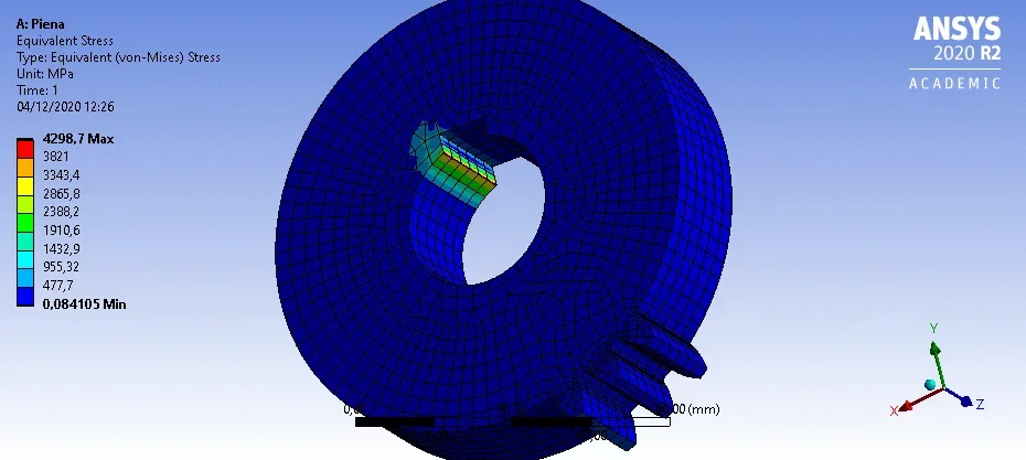
I have to make simple static simulations on dense wheels.
the simulation consists of:
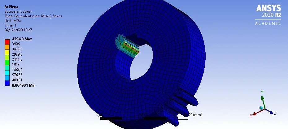
- application of a linear distribution along the side of the tooth at a distance from the known center.
-the wheel is bound by a recess along one side of the tab seat.
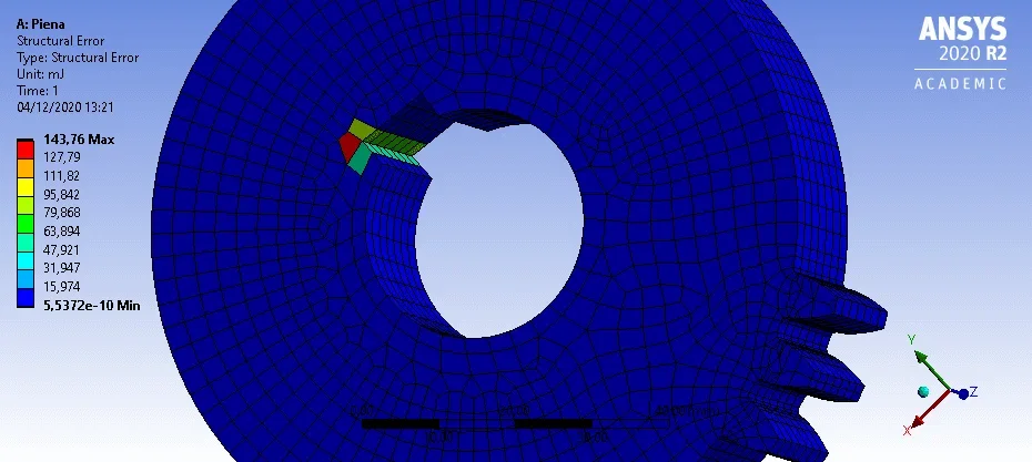
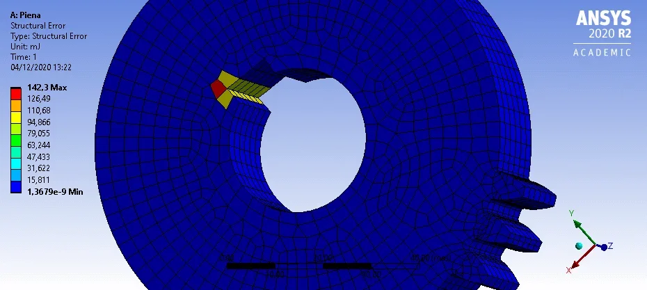
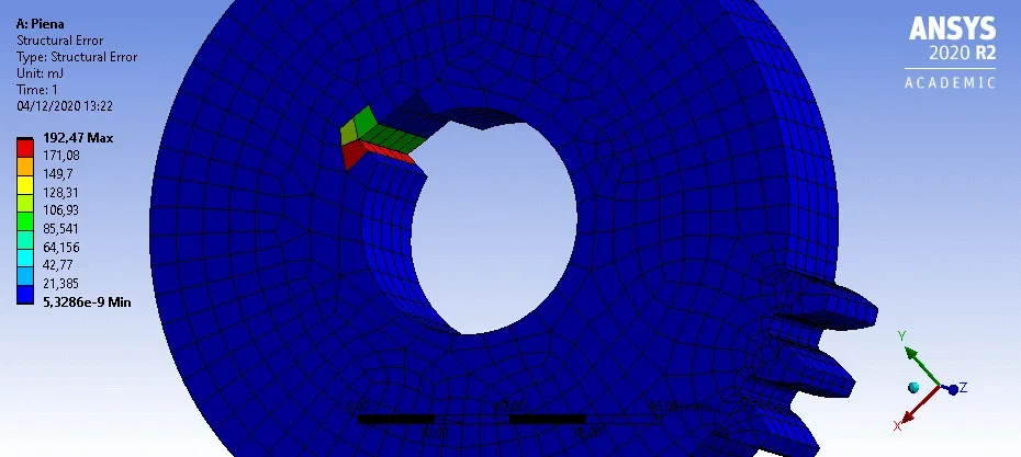
the problem is this: changing the resolution of the mesh changes the equivalent voltage state of von mises, which presupposes that a greater mesh finesse is necessary until it reaches convergence. However, I cannot assign to the solutor the task of assigning the mesh dimension as, automatically, a number of elements is created higher than that allowed by the academic version of the software.
At least I can use the automatic convergence function by redefining the mesh cyclically because I get the same error.
then, I thought to redefine the mesh manually in the areas of interest identified by evaluating the "mistake" of the voltage state. (laughing) )
However, I cannot define mesh in this sense, making it more enduring in areas of interest. I tried with the "body sizing" and "sphere of influence" function but I do not get the desired result or get the error that I bring back:
"the selective body meshing is not being recorded, so the meshing may not be persistent on an update. if you want to record the order of the body meshing, please use the mesh buried to track the meshing steps. please see selective meshing documentation for more details."
How can I proceed? I attach some images for greater clarity.
thanks to anyone who can help me!
I'm learning to use ansys at this time so I apologize in advance if the problem I'm experiencing is simple resolution. I can't find a way out on the internet.
I have to make simple static simulations on dense wheels.
the simulation consists of:
- application of a linear distribution along the side of the tooth at a distance from the known center.
-the wheel is bound by a recess along one side of the tab seat.
the problem is this: changing the resolution of the mesh changes the equivalent voltage state of von mises, which presupposes that a greater mesh finesse is necessary until it reaches convergence. However, I cannot assign to the solutor the task of assigning the mesh dimension as, automatically, a number of elements is created higher than that allowed by the academic version of the software.
At least I can use the automatic convergence function by redefining the mesh cyclically because I get the same error.
then, I thought to redefine the mesh manually in the areas of interest identified by evaluating the "mistake" of the voltage state. (laughing) )
However, I cannot define mesh in this sense, making it more enduring in areas of interest. I tried with the "body sizing" and "sphere of influence" function but I do not get the desired result or get the error that I bring back:
"the selective body meshing is not being recorded, so the meshing may not be persistent on an update. if you want to record the order of the body meshing, please use the mesh buried to track the meshing steps. please see selective meshing documentation for more details."
How can I proceed? I attach some images for greater clarity.
thanks to anyone who can help me!