• This forum is the machine-generated translation of www.cad3d.it/forum1 - the Italian design community. Several terms are not translated correctly.

steel beam sizing

  • Thread starter Thread starter stunt88
  • Start date Start date

stunt88

Guest
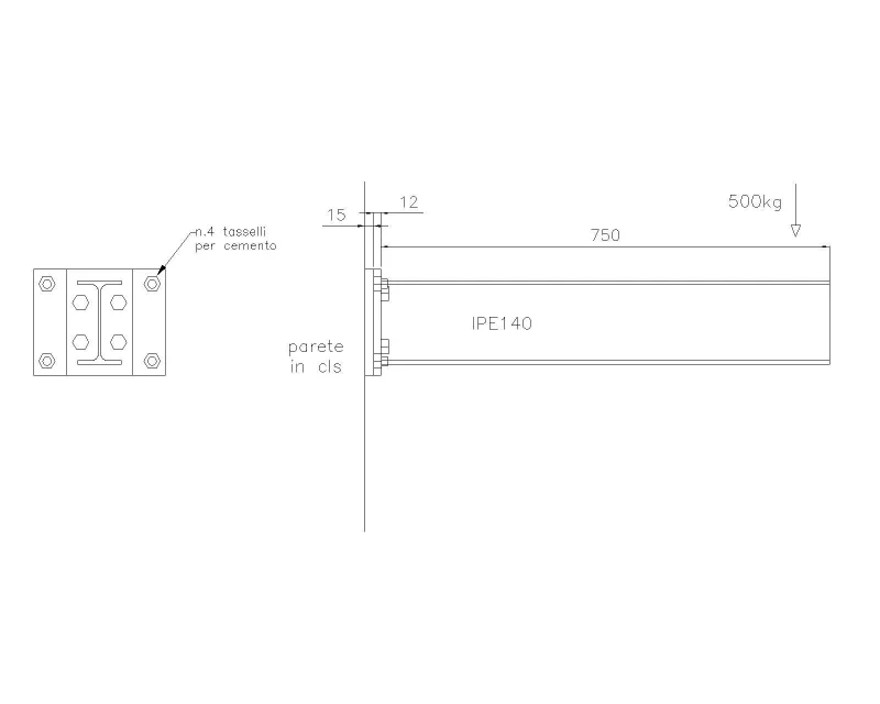
Good morning to all, I ask you kindly if you can give me some tips for the sizing of the beam indicated in the attached drawing.
It is an ipe140 beam with concentrated load anchored to a wall-mounted counter-plate with 4 male holes.
I would like to understand how to size anchors (diameter and length bolts, dowels etc.)
 

Attachments

  • es. trave-Model.webp
    es. trave-Model.webp
    16.7 KB · Views: 49
first of all determines the stresses on bolting.
you will have the v cut given by the sum of the weight of the beam and the force applied to the extremity.
and therefore the moment given by force to the extreme for the length of the beam more the moment due to the weight of the beam.
If you work at limit states will be something like:
ved = 1.3 x p x l + 1.5 x f
med = 1.3 x p x l^2 / 2 + 1.5 x f x l
the cutting force on the single background is simply: fv,ed = ved / n where n is the number of backgrounds (4 in this case).
while for axial force you can choose how to solve. I normally consider the behaviour of the plate analogous to a section of reinforced concrete (so with deformable plate) and echo from there the traction. you can also give back to the idea of the indeformable plate and consider that the rotation of the plate takes place around one of its edges.
wishing you could even more simply round the torque arm to 0.9d quantity where d is the height of the plate minus the distance from the edge of the row of bolts. it is not very different to use directly the arm given as an interasset between the bolts. from your drawings, it seems to me that the whole thing is about 140mm.
therefore, very simply: ft,ed = med / ( 2 x 140 )
of course adapts the units of measurement. the 2 is present because there are 2 backgrounds.
at this point are known the stresses on each single background. you just have to take the fischer tables and taking into account any reductions due to the distances between the wallpapers, the type of concrete etc. etc. you can choose the right wallpapers.
I recommend: add at least 20 or 30mm to the results of the tables to be sure to exceed the unarmed area of the wall.
 
Hi.
1) What does this term mean?
2) how do you plug a plate into another muted plate? Do you have any predispositions? Do you have executive details?
 
I didn't notice he was doing such a job.
the only way to do what you want is to weld pins on the plate already connected to the wall or weld the new plate to the old. I don't understand why.
Just one plate and go.

p.s.
I think fischerata is for the use of fischer (mechanical or chemical did not specify it).
 
x fischerata I mean anchored by mechanical or chemical dowels. However the concrete anchored plate must be equipped with 4 threaded holes to allow the assembly of the beam, this x allow the disassembly of the beam at any time
 
a good book of construction science or a manual. If you already know how to move, college dispenses are good.
- fixed beam solution, determining von mises effort and comparing it with the admissible solution
- verification of traction bolts and cut according to eurocidice 3 uni en 1993-1-8
- verification of traction and cutting wall dowels

I would say that everything is feasible to normal.
then you can check with a fem.
 
in this case the most serious problem moves.
you can also solve it by means of calculation programs made available by fisher, hilti and similar.
but the real problem you will have thinking that the traction effort generated by the ram to the disaster on the upper pins of the counterplate, must be brought by the only threads of the pins.
much better to use more long (shortened rods) and then transfer efforts through these, not through a threaded hole.
thanks x the answer. also x me is definitely better to transfer efforts on the wallpapers, but the customer wants a structure that must be able to disassemble and reassemble at any time. It is clear that the upper screws work so much at traction is I wanted to know their size. For example, are they good m16 x15?
 
to lighten the load on the screws can be soldered, after the positioning of the beam, under the beam plate. of course the plate fixed to the wall will have to be greater than about twenty millimeters (10mm of dowel+10 welding)
 
Indicative
neglecting the weight of the structure
cutting force=5 kn
moment flench=4 knmt

interasses 4 scales 140 mm
4 screws 80 mm

traction force on 1 background=14.5 kn
traction force on 1 screw=25 kn> could be enough even a m12 8.8, if you put m16 better, but I would use a thick plate 20mm instead of 15

I'll put some tits.
Hi.
 
the moment produced by the beam must be equal to the moment produced by the background
Hi.
 
hello to all, I appeal to this discussion to expose a doubt. once you get those that are the binding reactions on bolting, in case you had a fixed structure through two symmetrical fixing zones (image allego) how should you behave?
what I would think would be to consider the cut on the bolting divided on each single bolt present (considering both fixing areas), so if each area has 4 bolts, the cut stress for each single bolt will be the overall cut / 8 bolts. As for the couple acting on the whole bolting, I would consider it as a pair of forces distributed equally on both areas the bolts of the upper zone would be stressed in traction, in addition to the precarious also to an additional traction force due to the pair, while the bolts of the lower area would be pressed in traction, as well as their precarious also by a compression force due to the couple agent on the bolting.
would be correct? Am I neglecting something?

I hope I have expressed the concept clearly and understandably.
thanks to who will answer.schema_.webp
 
hello to all, I appeal to this discussion to expose a doubt. once you get those that are the binding reactions on bolting, in case you had a fixed structure through two symmetrical fixing zones (image allego) how should you behave?
what I would think would be to consider the cut on the bolting divided on each single bolt present (considering both fixing areas), so if each area has 4 bolts, the cut stress for each single bolt will be the overall cut / 8 bolts. As for the couple acting on the whole bolting, I would consider it as a pair of forces distributed equally on both areas the bolts of the upper zone would be stressed in traction, in addition to the precarious also to an additional traction force due to the pair, while the bolts of the lower area would be pressed in traction, as well as their precarious also by a compression force due to the couple agent on the bolting.
would be correct? Am I neglecting something?

I hope I have expressed the concept clearly and understandably.
thanks to who will answer.View attachment 61823
the reasoning seems correct to me, I think you have the stress cut only if the pull force of the 8 screws multiplied by in friction coefficient of the two plates fails to counter the vertical force. but perhaps for safety it is better to consider it.. I don't know the regulations about it, maybe good mechanicsmg can be more help!
 

Forum statistics

Threads
44,997
Messages
339,767
Members
4
Latest member
ibt

Members online

No members online now.
Back
Top