• This forum is the machine-generated translation of www.cad3d.it/forum1 - the Italian design community. Several terms are not translated correctly.

synchronization gearbox

piff91

Guest
Good morning to all,
premise, I am a novello of solidwork but I like the mechanical design and I like to complicate my life. only amateur use.
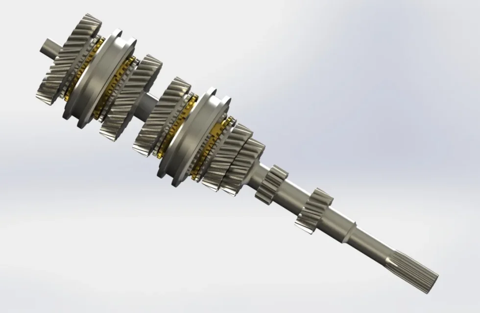
after finding measurements on the internet or measuring some spare parts, I managed to draw the primary tree, the crazy gears, the synchronizers and the sliding sleeve.
my question is how do I couple and make the whole complex functional?
the sliding sleeve moves moving the synchronizing ring that in turn, through conical coupling, goes to brake the crazy gear and then I don't know how, the teeth mate.
solidwork allows you to do this?Albero primario con ingranaggi.webpManicotto rigido e scorrevole.webpSINCRONIZZATORE-CAMBIO 3 4..webpI leave some photos/image attached.
 
Oh, God, you started using it six years ago, your newbie shouldn't be.
more than anything else is asked why if the question is on solidworks open the discussion on automotive .. mysteries
 
Oh, God, you started using it six years ago, your newbie shouldn't be.
more than anything else is asked why if the question is on solidworks open the discussion on automotive .. mysteries
true, 6 years ago, but then I no longer used it for life change and little performing pc.
I thought automotive as I did not check there was a special section for the software.
I ask if there is any moderator that can move the post in the right section. or should it be deleted and reinstateed? Sorry

Thank you.
 
must be asked to a moderator by message or recalling and mentioning it.
the sliding sleeve moves moving the synchronizing ring that in turn, through conical coupling, goes to brake the crazy gear and then I don't know how, the teeth mate.
if you don't know how it works how you replicate the couplings in solidworks?
 
Remember that with all parametric cads there are two scenarios:
- static constraints in configuration where you will put the constraints to lock in place that you will decide (engracing a march, synchronizing etc).
- motion analysis or simply animation, is something where you move the various elements to see with or without physical contacts, the behaviors of the various elements

in both cases there are on the online guide and on the web several tutorials to see how to use the modules or commands of solidworks.

clearly you must know the mechanical behavior of your object to bind it correctly.
 
It is therefore not feasible that type of coupling with "condition", right?

I did:
in the primary tree attached in photo, I made the outside of the bearing as a fixed part.
the internal synchro is coupled (on a plane) with the shaft and the synchro ring is coupled with the int sync on a plane. They rotate, therefore, both with the tree.
the gear of the gear is crazy therefore free to rotate.

what I can't do is:
the outer sleeve, when operated, pushes the synchronizing ring to the gear and this uniforms it to the rotation of the shaft (conical coupling).
the outer sleeve, then, ends up gearing the teeth placed on the gear and bind the same to the rotation of the tree.
Did I make the idea?
 
you can do it with the advanced dynamic simulation module using gravity and contact between the bodies.
definitely not a trivial thing to set up.
with the static constraints of the model you cannot make conditions like that.
 

Forum statistics

Threads
44,997
Messages
339,767
Members
4
Latest member
ibt

Members online

No members online now.
Back
Top