• This forum is the machine-generated translation of www.cad3d.it/forum1 - the Italian design community. Several terms are not translated correctly.

technical drawing exercise aid

MF21

Guest
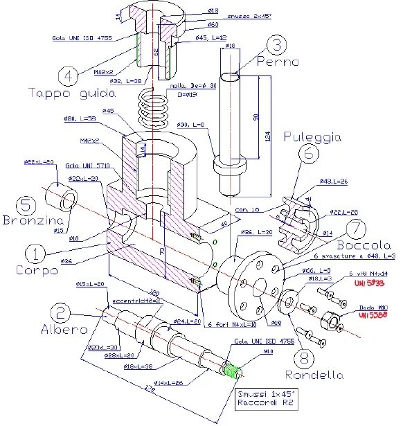
Hi, I'm a spacecraft engineering student and I'm new on the forum. I am preparing the industrial technical drawing exam and if possible I would need help on an exercise, which I attached in the post. Attached I also entered as for now I am carrying out the exercise, performing the first 4 extrapolated pieces. My doubts are as follows:
* in the track of the exercise asks to insert the tolerances in the drawing, but how should these be calculated? a my thought was that, taking for example the connection between the number 1 and the shaft 2, to subtract to the maximum width of the circumference of the piece (diameter 36) to that of the larger cylinder of the shaft (diameter 28 with eccentricity of two) getting a maximum dissection of 2 mm. is it right as reasoning or is it completely wrong as a road?
* in the drawing there are quotations of gorges and threaded pieces. for threaded pieces I found a table on the book which for example, for m42 x 2 tells me that the drilling diameter is 40 mm, but from the theory I know that it is 42 refers to the nominal diameter and 2 the step, what is the measure I have to adopt on the drawing? As for the throat, I did not find any connection to the drawing that helps me find the size of the throat, how should I proceed? also, in the design as listed compartment? with the norm or size in mm?
* the specific track to extract unified details, among these should I draw only pieces ranging from 1 to 8 or even pieces like spring, screws and bolts?
 

Attachments

first of all you have to understand the assembly of the assembly; you have a cad, use it to draw every single piece and then try to rebuild everything and it will be clearer both the operation and where it is neccesary to make tolerances.
* Diameter 36 is not tied to the shaft except in the fiction of allowing the rotation of the eccentric. analyzes all elements
*in the design there is always the nominal diameter and never, the bottom of the crest i.e. the thin lines; you specify the step if different from the defined one big.
the sobo gorges regulated according to their use: for grinding or threading; defined the function you will have the reference standard. the quotation can be indicated even only with the norm, but if you were a lathe or programmer how much pleasure would you have to stop the machine to look for the measurements on a book?
*according to you, what does unified particular mean?

I forgot, except the first other questions have already been discussed in other threads; do research in the student section and you will have further clarifications to these and other doubts.
 
Last edited:
Thanks for the help. I checked after writing the post and the answer to the question about the thread I found it on the forum, I apologize for asking something superfluous. regarding the cad, I do not hold it, being out of course I have expired the free trial of one year autocad as I used it last year, when I followed the course.
In case, drawing the complete piece would only serve me to better understand tolerances or would it also be to be delivered as part of the exercise? (as he asks only to extract them)
 
there are free cads both 2d (nanocad) and 3d (freecad).
if you can't/you want to draw the assembly you need to learn how to read the explored well.. the tree you mentioned where it is mounted, with what does it mate?
In case, drawing the complete piece would only serve me to better understand tolerances or would it also be to be delivered as part of the exercise? (as he asks only to extract them)
I hoped it was obvious, having written it, that making the assembly only serves to understand its functioning. How can an outside person know what you have to deliver?
 
Sorry, it's that having the track ahead I assumed I wrote it. the track is as follows:
from the explosive view of the axieme below illustrated extract the unified details and represent them in all the views and sections strictly necessary. quotating details also indicating dimensional tolerances on the features that require it to ensure the proper functioning of the entire device.
operation of the point group.
the present point system allows the pin (3) to flow vertically, alternately, in the appropriate internal seat of the body (1) because of the thrust of the eccentric present in the central part of the tree (2). Thus following the rotation impressed by the shaft by the pulley(6), the pin(3) moves freely vertically contrasted by the helical spring which is blocked in its seat by the guide cap(4). the tree (2) is free to rotate in the seats constituted by the bronze (5) and the flangeed bushing (7). The latter is fixed to the body (1) by means of n.6 screws with a head.
 
with this last description, you understand completely the operation.
to ensure this, different tolerances must be placed on the coupling of organs in rotational or linear motion, sliding organs blocked with screws and organs blocked by interference.
This is the main sum of the problem.
the views and sections, must be clear, with bold line, with right quotation, and sufficient to make understand in complete way, as the piece is done.
the details drawn by you, are full of errors.
two of these:
-manca line in view in section, (gravissimo)
-The quotas must always be placed above the quotation line, the actual ones place after turning the sheet of 90° clockwise.
 
thank you very much for the help, regarding the line in view in section is not reported in the photo, but I put it in the drawing, while I was not aware of the norm of the position of the quotas, you have been very helpful. Are there any other particular errors to be highlighted?
with this last description, you understand completely the operation.
to ensure this, different tolerances must be placed on the coupling of organs in rotational or linear motion, sliding organs blocked with screws and organs blocked by interference.
This is the main sum of the problem.
the views and sections, must be clear, with bold line, with right quotation, and sufficient to make understand in complete way, as the piece is done.
the details drawn by you, are full of errors.
two of these:
-manca line in view in section, (gravissimo)
-The quotas must always be placed above the quotation line, the actual ones place after turning the sheet of 90° clockwise.
 
ciao @mf21,

the couple you have to pay attention to are those:
1) bronzine (5) body (1) will be with interference for which the tree, the outer diameter of the bronze, will have to be a little larger than the hole in which it resides (see here ideal coupling bronzina / pin and bronzina / boccola frame )
2) the tree (2) bronzine (5) will be with game for which the tree will have to have a diameter a little smaller than the hole (see same discussion above)
3) Tree (2) with flanged bushing (7) same first speech with game
(4) the tree (2) with the pulley (6) that having to rotate the tree (2) must be mounted with interference because I do not see keypads or tabs suitable for purpose
5) the pin (3) with the body (1) must flow (and therefore play) in diameter 16 of the latter
also evaluates the lengths l=20 and l=26 of the tree. You don't have to shut it down otherwise nothing turns.
Look first at the document that I attach to you.
 

Attachments

thank you very much for the help, regarding the line in view in section is not reported in the photo, but I put it in the drawing, while I was not aware of the norm of the position of the quotas, you have been very helpful. Are there any other particular errors to be highlighted?
If you want to use squares, do not use colored millimeter sheets, because with the thin sign, you do not understand anything, you can use the 5 mm square white sheet.
each design must respect the positions of the orthogonal projections, it must have the name of the detail, the scale, and the graphical indication of the European system.
for mast- pulley mating, since neither the grain nor the stick, nor the tab, invented the conical coupling, even without signaling the error of omission, you will be beautiful figure and you will deserve an extra point.
I would not do the coupling with interference because if you loose it doesn't work anymore, but if you don't loosen up, you don't parade anymore.
arrows go very sharp, like the Indians.
the bevels at 45°meglio indicate them with the tilted line with the written text...
m 42 x 2 indicates a metric thread with a nominal external diameter of 42mm. in practice slightly lower for the male, both to avoid interference, and to ensure entry into a hole diameter 42 h.
I would like to see the corrections made. Bye.
 
ciao @mf21,

the couple you have to pay attention to are those:
1) bronzine (5) body (1) will be with interference for which the tree, the outer diameter of the bronze, will have to be a little larger than the hole in which it resides (see here ideal coupling bronzina / pin and bronzina / boccola frame )
2) the tree (2) bronzine (5) will be with game for which the tree will have to have a diameter a little smaller than the hole (see same discussion above)
3) Tree (2) with flanged bushing (7) same first speech with game
(4) the tree (2) with the pulley (6) that having to rotate the tree (2) must be mounted with interference because I do not see keypads or tabs suitable for purpose
5) the pin (3) with the body (1) must flow (and therefore play) in diameter 16 of the latter
also evaluates the lengths l=20 and l=26 of the tree. You don't have to shut it down otherwise nothing turns.
Look first at the document that I attach to you.
Thanks for suggesting the links. I used the following tree- hub links, based on the site Hole-shaft tolerances, reading the various descriptions of the couplings and using the ones that I seemed most suitable for the various shaft-hole connections, in particular I used for the connection (1)bronzine-body 22 h7/p6, for (2) tree-bronzine 15 g6/h7, for (3) tree-mouth 36 h7/g6, for (4) tree-puleage 14 h7/n6 and finally for (5) pin-body 18 f8/h7
 
If you want to use squares, do not use colored millimeter sheets, because with the thin sign, you do not understand anything, you can use the 5 mm square white sheet.
each design must respect the positions of the orthogonal projections, it must have the name of the detail, the scale, and the graphical indication of the European system.
for mast- pulley mating, since neither the grain nor the stick, nor the tab, invented the conical coupling, even without signaling the error of omission, you will be beautiful figure and you will deserve an extra point.
I would not do the coupling with interference because if you loose it doesn't work anymore, but if you don't loosen up, you don't parade anymore.
arrows go very sharp, like the Indians.
the bevels at 45°meglio indicate them with the tilted line with the written text...
m 42 x 2 indicates a metric thread with a nominal external diameter of 42mm. in practice slightly lower for the male, both to avoid interference, and to ensure entry into a hole diameter 42 h.
I would like to see the corrections made. Bye.
I have changed the odds placed below or placed counterclockwise, only in the second drawing I left them as they would create too many canceled lines creating confusion in the piece, but I have in mind to remake time allowing as I am tight with the time for the exam. I tried to point out as much as possible some arrows too angled. with regard to the scale and the European system are to be written in the cartilage that I still have to paste on the table, in fact I left at the bottom of each sheet the space to paste it. As for the bevels I prefer to quote them so, since both on the slides of the prof and on the book are listed in this way, I do not doubt your advice, indeed thank you, but I prefer to respect the guidelines of the professor.
a further thanks to all the components of the forum that helped me, in addition to the drawing in question you helped me understand better, in general, how to draw a technical design, and this will help me for the next drawings and for the examination
 

Attachments

read some old discussions because you are making mistakes that have already been discussed several times.
summarily:
wrong quotation, deficit and unwilling
representation of the wrong entities (the projections at first glance seem correct).
in the forum and on the net there is the world of material to study the basics of representation and technical drawing regulations; the quotation is refined with experience and practice, but in this case you must practically only copy what you see in the drawing
 
I can't see almost anything, not even with the lens, but I see very well that in the section of two different coaxial diameters, among them there is a edge in sight that you didn't track.
I had reported it to you as very serious, but you didn't take it into account.
If we give you the suggestions, it would be good for you to follow them, or at least that I verify them, because at the exam we will not be there and mistakes will be paid.
 
I will be fixed....but the arrows of the quotas in mechanical technical drawing are done at a closed angle, acute ....15-20 degrees....not 90 degrees potatos.
Why even copying from books is difficult?
 
Thanks for the help. I checked after writing the post and the answer to the question about the thread I found it on the forum, I apologize for asking something superfluous. regarding the cad, I do not hold it, being out of course I have expired the free trial of one year autocad as I used it last year, when I followed the course.
In case, drawing the complete piece would only serve me to better understand tolerances or would it also be to be delivered as part of the exercise? (as he asks only to extract them)
Hello mf21,
try to use onshape is a free cad and you work directly online. It was very useful during studies to start modeling, but never having made the boards I can't tell you if the software gives you the chance to build them.
for the design I recommend you to prend the "designer's manual" of the hoepli, really very useful and to the hand, I still use it now at work.
 
there is also freecad which is free and can be a good base to start. model and table.
then there are student versions of solidworks and inventor.
 
good evening mf21, a small advice I give you is to avoid drawing on millimeter paper and to use the classic white sheets that make everything more pleasant and fatigue less the view.
I associate myself with other colleagues regarding freecad that if I don't remember badly should allow to get the tables in 2d.
 
ciao @mf21 One thing. very important in the drawings is the cartiglio, an integral part of the drawing, in which the General tolerances which are applied where not expressly indicated. depending on the type of accuracy required, fine-medium-coarse, there are tolerance fields that can lead to errors.
In fact, there is no exact measure, there are measures that vary within tolerance.
I attach a table on the net with these tolerances.
 

Attachments

ciao @mf21.
the m42x2 "fascia" is not indicated on the guide cap 4 (the same applies to the internal thread present in the body 1). You know how much it is?
 

Forum statistics

Threads
44,997
Messages
339,767
Members
4
Latest member
ibt

Members online

No members online now.

Back
Top