• This forum is the machine-generated translation of www.cad3d.it/forum1 - the Italian design community. Several terms are not translated correctly.

torque stiffness

  • Thread starter Thread starter pisco
  • Start date Start date

pisco

Guest
Hello.

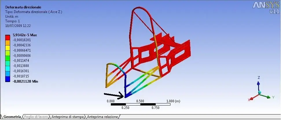
I press that they are at the first simulations in ansys 11 and should evaluate the torsion rigidity of a structure (frame in traliccio of hollow section profiles). the design was created in solid edge v20 then exported to ansys and applied the relative constraints and loads on points of interest after generating the mesh. Now I would like to know if it is possible to evaluate the rotation of the structure between the two sections i.e. the cross section and the one where I applied the loads (carichi that generate me a pair).:frown:

starting the simulation of a very simple circular section beam subjected to a torque moment on one end and an interlock in the other I carried out the various simulations, but in evaluating the deformation the program shoots me out all values with a unit measuring m/m:confused:
Would someone tell me how to cover those results? :frown:

Thank you in advance
 
grz for the answer but I already knew that the deformation epsilon=al/l,
Perhaps I was not clear in exposing my problem I would like to determine the rotation of the structure between the constraint section and the section where I applied the load.
 
Sorry, I didn't understand the problem. then, if in dof plotted postprocessor, you can find the total shift vector. If not, I remember that in the dynamic fluid tutorial it was explained how to follow the path of a chosen point. I believe that by introducing points on your structure, you can also identify the relative rotation through the software: once you know x and y or z, applying simple trigonometric equations you can find the corner. cmq try to consult the tutorial and see if in this way solve the problem. in case I have to find a more effective alternative path, I will be happy to communicate it. Let me know if this works.
 
:frown: Hello excuse me but in v11wb I can't find the plot dof
I would have tried to label a knot by getting the cordinate of the undeformed structure and then label the same knot in the deformed 1:1, then make the difference between the two coordinates, but I know it is a great caxxata.
 
I was referring to the classic ansys interface. with wb I have no experience, so in practice I can't suggest where to go to find the commands...the classic interface is more osticated and less intuitive, but it lets more design choices. for certain advanced models then I think it is the only way (for example for composite materials or all those analyses that require a minimum of programming)
 
okk thank you again for the advice, tomorrow I will try to solve this problem, in case I will let you know .
 
Hello,
I have attached an image of a part of the structure on which I am carrying out the tests. the command you recommended postprocessor -> plot-> dof on my interface I couldn't find it.
In the image I simulated the deformation along the z axis, my problem is to determine the long z shift of a point in the area where I highlighted with the arrow, then through the trigonometry to the rotation angle.
Now I can't understand that 0.0021128 (m) what it refers to or better if it doesn't hit anything with what I want to determine:confused:
 

Attachments

  • Immagine1.webp
    Immagine1.webp
    36.6 KB · Views: 36

Forum statistics

Threads
44,997
Messages
339,767
Members
4
Latest member
ibt

Members online

No members online now.
Back
Top