• This forum is the machine-generated translation of www.cad3d.it/forum1 - the Italian design community. Several terms are not translated correctly.

turned finish

  • Thread starter Thread starter volaff
  • Start date Start date

volaff

Guest
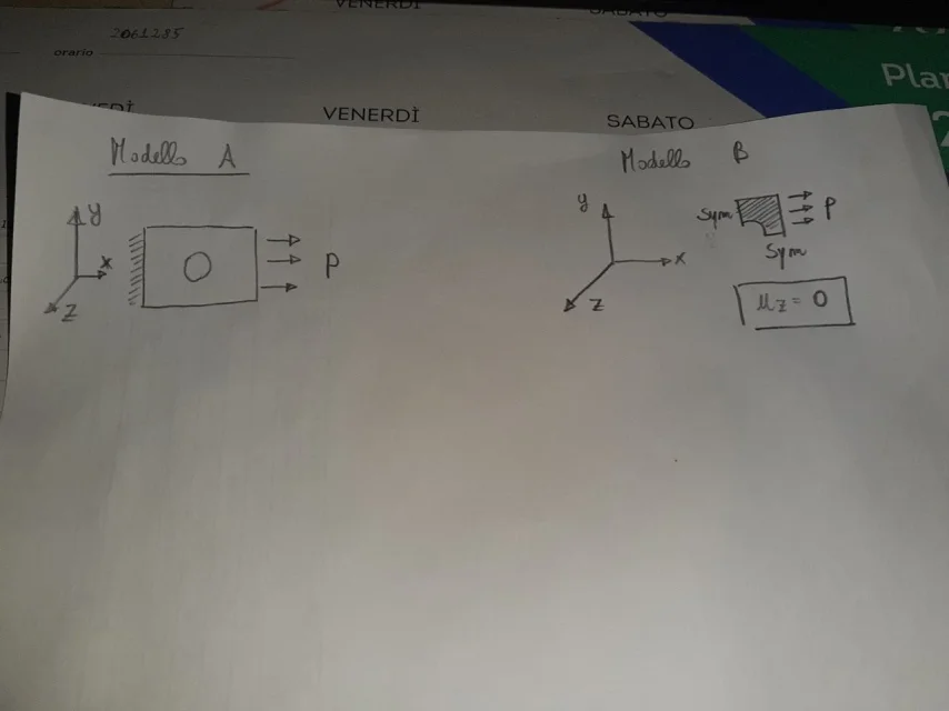
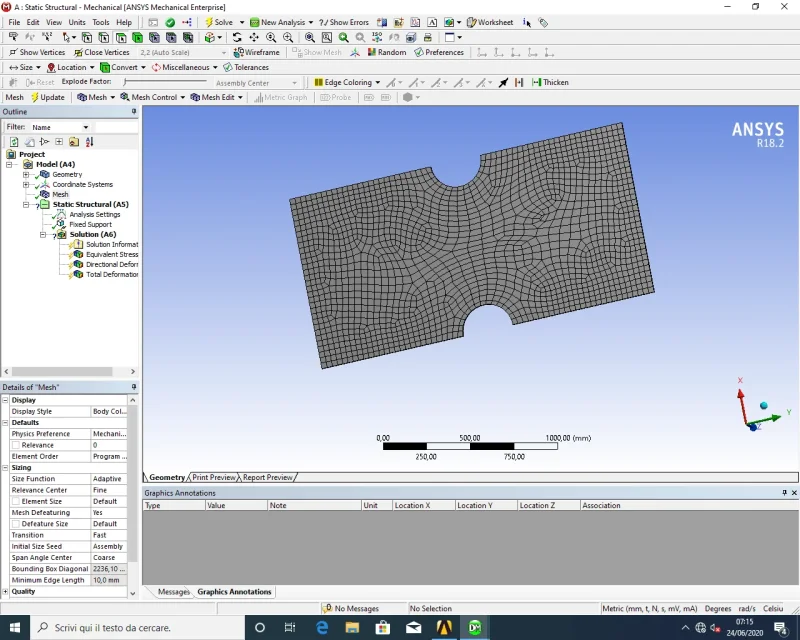
hello girli, I wanted to start using ansys workbench by solving a small academic exercise below.
1592976073933.webpI was able to model everything but now I should simulate the stinging moment at the end of the plate.

going to memory that it can be simulated as a concentrated force at one end (but this would not be properly corrected as we will give rise to a singularity point) or tramire a triangular load (but here I do not remember that values give to the ends of the same).
advice?

thanks to everyone in any case!
 

Attachments

  • Immagine.webp
    Immagine.webp
    141.9 KB · Views: 21
an asymmetric mesh that shapes a component with two axes of symmetry leads to numerical artifacts to all spy. We should work more on modeling.

said that, why not apply a moment to the face at the top of the plate? I mean the face that in the schematic design is orthogonal to the sheet and looks upward.
 
Bye.
I wanted to work by step: first on the global model and then on the one obtained using double symmetry.

the problem of applying the time was to understand how to simulate it beyond entering it with the command "moment".
in truth I did and the value obtained is distant from that actually calculated by my colleagues,
 
You must use a link element that connects all the knots of the face to which you want to apply the moment to a single knot, and then apply a single moment to the knot. in nastran queesti elements are called rbe2 for rigid ones and rbe3 for flexible ones.
in ansys I don't know what they call, but they exist, maybe this link can help. : with regard to the comment of lightning, if you divide the faces according to the axes of symmetry, you should come a mesh almost symmetrical.
 
thanks for the answers.
the software allows you to apply a moment by selecting an area.
As soon as I can verify.
I am doubtful of having applied a moment around y i.e. torque and non-flecting (refer image post #1)
 
good Sunday to all, while trying to resurrect this academic exercise, I came across another exercise where it was always necessary to exploit the symmetries (plate with central hole).
I found an old pdf that helped me understand how to do it.
once I set the double symmetry, in order to find the solution, I had to impose shift along z null and found written "this boundary constraint is necessary to restrain the rigid body motion of model so that when we apply the we get only elastic deformation not a rigid body movement".

Is that correct?
excuse the question of Sunday:)

good start of the week to all.
 
in model b, the p indicated is the same as model a? the software establishes the true length to which it applies?
 

Forum statistics

Threads
44,997
Messages
339,767
Members
4
Latest member
ibt

Members online

No members online now.
Back
Top