ApeGana
Guest
Hello, everyone.
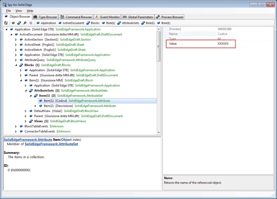
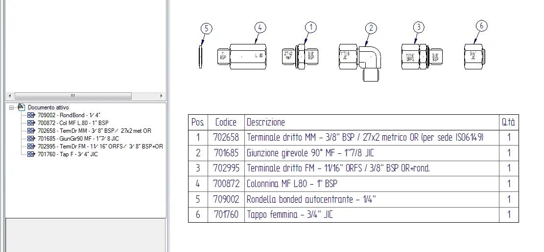
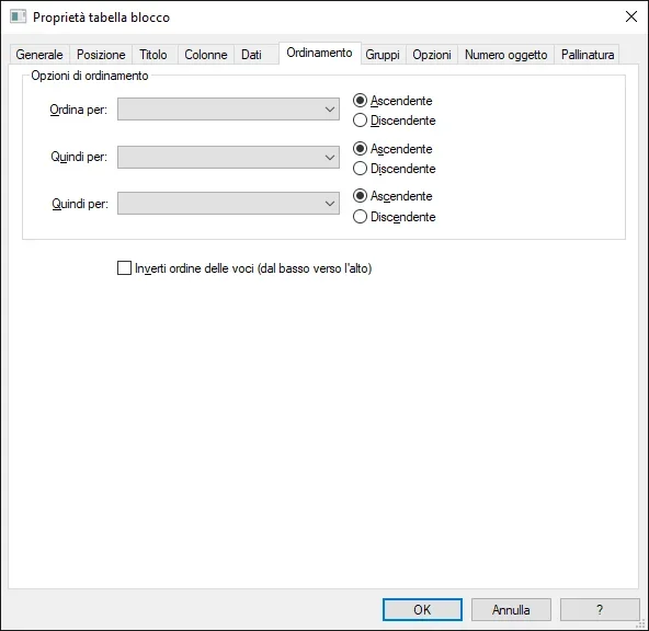
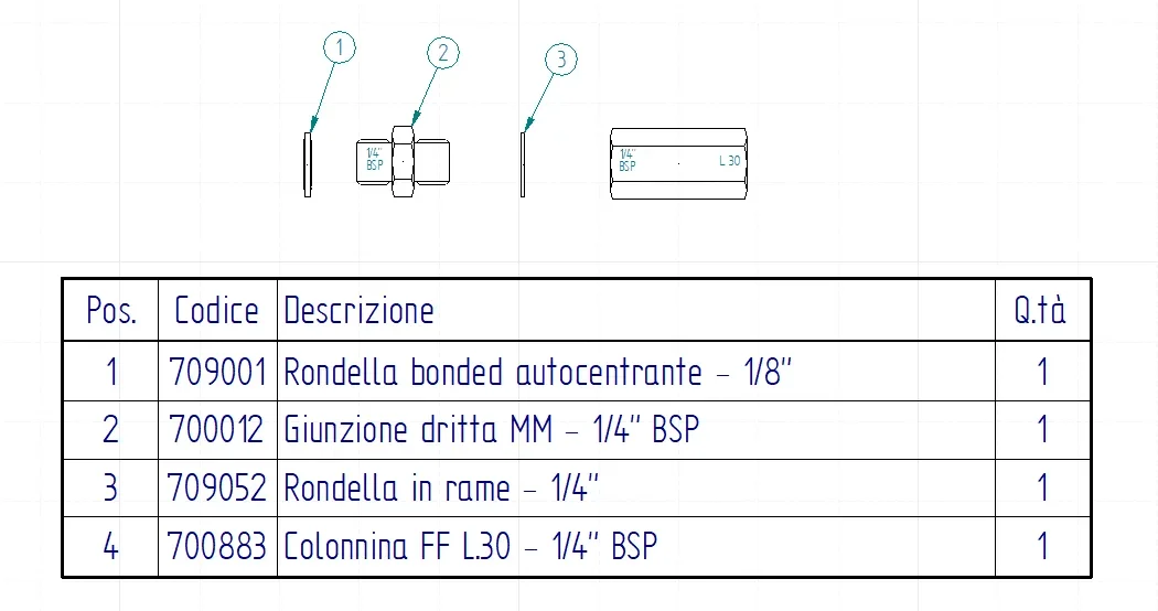
to make a series of hydraulic fitting schemes mounted on our groups, I was thinking (instead of modeling all fittings in 3d and assembling them on the totals) to draw simplified silhouettes in 2d as blocks to assign code and description as properties to be recalled on the separate parts (which in this case would be the block table).
I never used that system and tried to look for something here on the forum to get a little deeper before I decided, but I didn't find anything.
Is there someone using this kind of approach?
in particular the first two questions that have arisen are these:
- in the creation of the database of blocks / fittings, I see that to create a new one is not enough copy/paste of one already created and rename it because the name is not editable; you need after copying/paste unlocking it and redefining the top block, which makes you waste time. Did I run?
- I see that the blocks could be stored all within a single dft used as a "magazzino", or vice versa create a different dft to contain each new block/symbol/ragreement I must represent.
What is the most convenient way?

