While EVs are much quieter than traditional gasoline or diesel-powered vehicles, they are not completely silent. Some EVs produce noise from the electric motor, tires, and wind. This noise can still contribute to noise pollution, particularly in urban areas.
This article introduces a system simulation methodology to set up a model dedicated to noise and vibration early analysis. The “Electric Machine Noise and Vibration App” of Simcenter Amesim is a postprocessing tool capable of estimating electromagnetic forces, vibrations, and radiated noise within an electric motor, starting from an electromagnetic model created in Simcenter Motorsolve.
Noise generated by an electric drive
Electric motors can generate noise from two main sources: cogging torque and winding noise. Cogging torque is generated by the interaction between the permanent magnets in the rotor and the stator windings due to their slight misalignment. This results in a pulsating force that produces noise. Winding noise, on the other hand, is produced by the vibration of the stator windings when they are energized by the electric current. This is caused by the Lorentz force, which is produced by the interaction of the electric current in the windings and the rotor’s magnetic field.
At the same time, inverter control plays a significant role in influencing the noise generated by electric motors. The inverter, a crucial component in the EV powertrain, regulates the flow of electricity from the battery to the motor, controlling its speed, torque, and overall performance. However, its switching operation, characterized by rapid on-off cycles, can introduce undesirable noise emissions. The primary mechanism responsible for inverter-induced noise is switching harmonics. During the switching process, the inverter generates high-frequency electrical pulses that can radiate into the surrounding environment. These harmonics can manifest as audible noise, particularly at high switching frequencies.
The E-noise app in a nutshell
The “Electric Machine Noise and Vibration App” is designed to quickly and accurately evaluate the NVH performance of machines. The process to assess the noise of the electric drive consists in:
- running a Simcenter Amesim electric drive model along a given load case scenario
- assess the noise and vibrations of the drive from the simulated scenario within the e-noise app
From the model of Permanent Magnet Synchroneous Machine PMSM with spatial dependency operating in various load conditions, and the magnetic field in the airgap look-up table, the app builds a predicting model of the electromagnetic forces in the airgap. The magnetic information are coming from electromagnetic simulation results coming from Simcenter Motorsolve.
The app creates a predictive model of electromagnetic forces in the airgap of a Permanent Magnet Synchronous Machine (PMSM) operating under various load conditions. This is achieved by using a lookup table that contains magnetic field information obtained from electromagnetic simulation results from Simcenter Motorsolve.
The force density derived from this model is then applied to an analytical and structural model of the machine’s overall shape. By doing so, the app can predict the average vibration levels of the motor’s exterior surface. These vibration levels can be used to calculate the amount of radiated noise at a specified distance.
The 4 steps are:
- Export from Simcenter Motorsolve of the airgap radial and tangential magnetic field .
- Export from Simcenter Motorsolve of the Simcenter Amesim PMSM spatial dependency models for system-level simulation.
- Set-up of the Simcenter Amesim PMSM e-drive models including the inverter and machine torque controller.
- Assess the acoustic and vibration response of the machine with the electric machine noise and vibration app

This process has been applied to an electric drive close to the Nissan Leaf electric powertrain.
Description of the electric powertrain under investigation

The electric drive represented in this demo is like the Nissan Leaf electric powertrain.
e-Powertrain
The electric powertrain uses dynamic components for the electric machine, converter, and control.
The electric machines used in this study have the following main characteristics summarized in the table below:
| Leaf-like machine | |
|---|---|
| rotor type | Interior Permanent Magnet (IPM) |
| DC link voltage | 300 V |
| Base rms current | 320 Arms |
| Maximum torque | 180 Nm |
| Base speed | 4000 rpm |
| Power at base speed | 80 kW |
| Pole pairs number | 4 |
| Winding | 3 phase – lap winding |
| Slot number | 48 |
| First mechanical order | 24 |
| Second mechanical order | 48 |
| Geometry |  |
Table 1: Leaf-like electric machine main characteristics
The CAD and machine physical properties of this machine have been defined using the Simcenter Motorsolve to Simcenter Amesim export solution.
The Simcenter Amesim model parameters are entered in a non-linear model of a permanent magnet or reluctance machine with spatial dependencies. This submodel enables the simulation of the machine’s electromagnetic performance while considering the magnetic saturation and the spatial harmonic because of slots, winding configuration, and magnet shape.
Drivetrain
The model of the driveline is a series of inertias and springs which consist of:
- Rotor inertia
- Intermediate shaft inertia and stiffness
- Side shafts
- Tire stiffness
- Wheel inertia
- Vehicle mass
This decomposition leads to the following natural frequencies for this driveline:
| Frequency (Hz) | |
|---|---|
| Mode 1 | 9 |
| Mode 2 | 31 |
| Mode 3 | 2116 |
Table 2: Driveline modes
There is a two-stage reducer with a fixed ratio of 9.3. The first stage of this reducer also includes a transmission error assumption. This transmission error represents the micro geometry imperfections of the gear pair and acts as a source of harmonic excitation. The order of this excitation depends on the ratio of the gear pair and the number of teeth of the gears.
In our case :
Process to set up the noise and vibration analysis – Simcenter Motorsolve
All detailed steps to set up the noise and vibration analysis on this example can be found on a dedicated Knowledge Base document available at our support center.
Noise and vibration analysis
The load case scenario is a speed ramp-up of the electric machine.
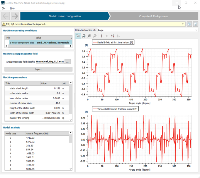
The figure below displays the PMSM noise and vibration app once the Leaf-like electric machine has been configured:

Figure 3: Leaf-like electric motor configuration
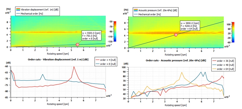
The 2 plots below display the Leaf-like motor vibration and acoustic response:

Figure 4: Leaf-like displacement (left) and radiated noise pressure (right)
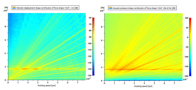
The 2 plots below display the Leaf-like motor force shape 4 contribution for vibration and acoustic response:

Figure 5: Leaf-like force shape 4 contribution for displacement (left) and radiated noise pressure (right)
Conclusion
In this demo example, we emphasize how to set-up a model dedicated to noise and vibration early analysis. It enables to:
- Compare distinctive electric powertrain designs.
- Assess the trends and potentially problematic frequencies including the mechanical drivetrain.
- Mitigate noise and vibration risk by adjusting, in an early stage, mechanical driveline configuration.
Going further
Additional features have been developed by our Simcenter Engineering and Consulting Services organization. They include:
- Calculating and displaying e-motor NVH performances above 10 kHz
- Exporting the noise and vibration results in ASCII format
- Compatibility with dual-star machines
- Replacing the analytical 1D model of the stator with a high-fidelity 3D model of the e-powertrain system:
- Based on FE reduced order model of structure and acoustics
- Allowing very fast NVH calculations at the system level (accounting for controls, switching frequency,..)

Figure 6: Advanced feature of PMSM noise and vibration app set-up process


