3DEXPERIENCE CATIA (different from CATIA V5) was introduced in 2014 with the 3DEXPERIENCE Platform. (We compare the differences between the two here.) In this article, we’ll cover some of the features and tools in 3DEXPERIENCE CATIA for assembly design, part design, drawing creation, sheet metal tools, and more.
3DEXPERIENCE Platform
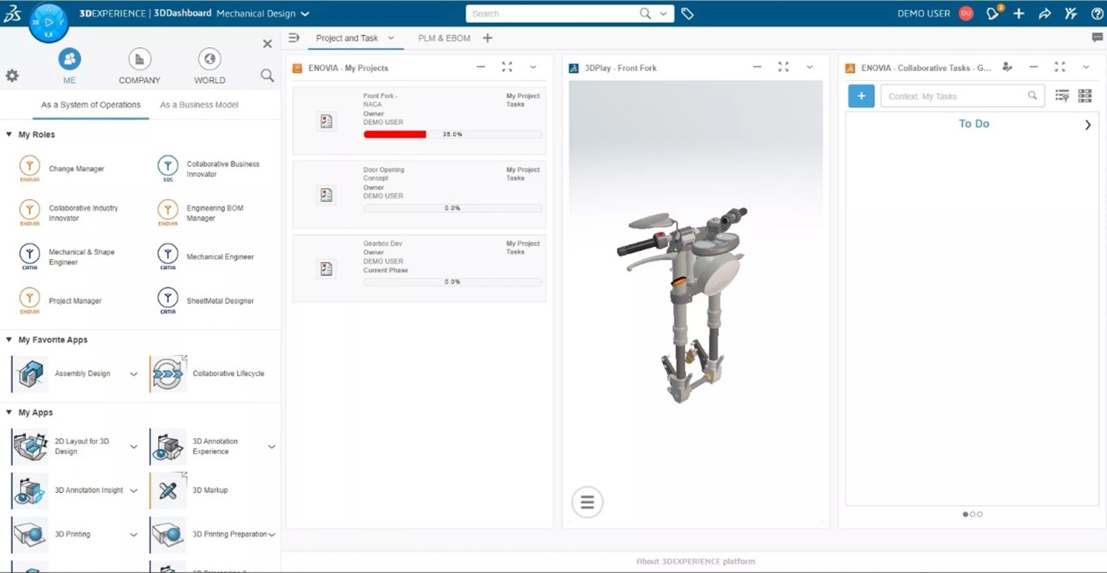
The 3DEXPERIENCE Platform is the backbone of 3DEXPERIENCE CATIA, giving it some advantage over the traditional CATIA V5. For smaller to medium-sized companies without ITAR requirements, a cloud version of the platform is a great option. Being on the cloud means Dassault Systemes hosts all of the licensing, platform, and storage space for you. For larger companies that want or need full control of their environment, an on-premise platform can be created. 3DEXPERIENCE CATIA includes two pre-requisite roles: Collaborative Business Innovator and Collaborative Industry Innovator.
The Collaborative Business Innovator is the primary role that grants any user in the company access to the Platform. The Collaborative Industry Innovator is an ENOVIA role with PDM/PLM capabilities and is essential for CAD data management users. Both roles can be accessed via a web browser anywhere and on any device, allowing quick availability to status updates, tasks, models, conversations, and more.
3DEXPERIENCE CATIA Part Design
Part Design in CATIA is extremely powerful and includes a variety of features like pads (extrudes), cuts, fillets, chamfers, holes, patterns, and more for designing mechanical components. The power of modeling has been rooted in CATIA from the start but is more intuitive and much easier to learn in 3DEXPERIENCE CATIA. (SOLIDWORKS users will recognize familiar interface cues, such as context-sensitive pop-up menus next to the cursor to help speed up modeling.)
With the Robot tool, quickly drag and drop sketches/profiles to create pads, cuts, or other features. The Semantic Painter quickly copies the details of a feature onto similar features. This is especially helpful when there are multiple features to modify.

Robot drag and drop to create features
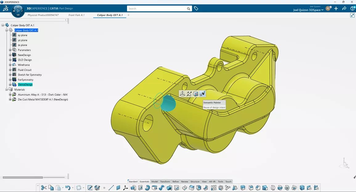
Semantic Painter to copy feature details onto similar features
Surface Design
3DEXPERIENCE CATIA surfacing is one of the big reasons other CAD users switch over and why most automotive, marine, and aerospace companies utilize the software.
The surfacing capabilities within 3DEXPERIENCE CATIA contain all the same functions as most other CAD packages but can resolve a lot of surfaces and surface combinations that others cannot. There are multiple levels of surfacing apps that users can utilize, even ICEM apps.
The robot and context-sensitive menus allow for quick surface modeling by utilizing drag and drop to create revolves, extrudes, fillets, trims, splits, and other typical operations based on selected entities. Modeling half of a model and then utilizing the Symmetry command can drastically speed up the design process.

Quickly trim surfaces by selecting appropriate surfaces to keep and using the context-sensitive menu
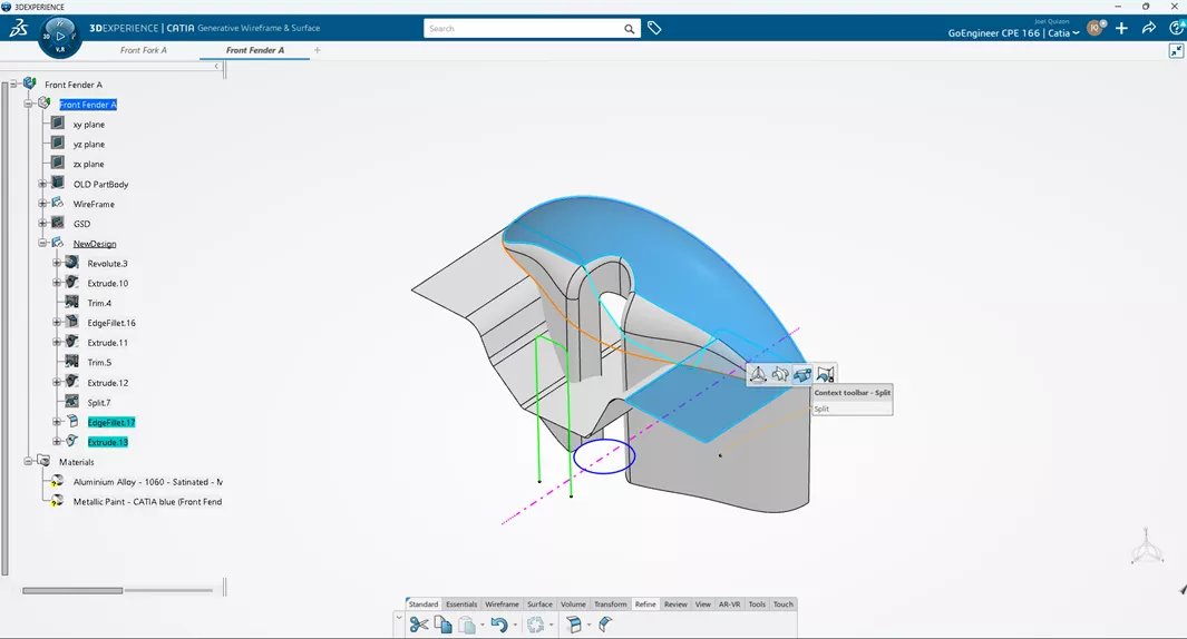
Split surfaces in 3D EXPERIENCE CATIA
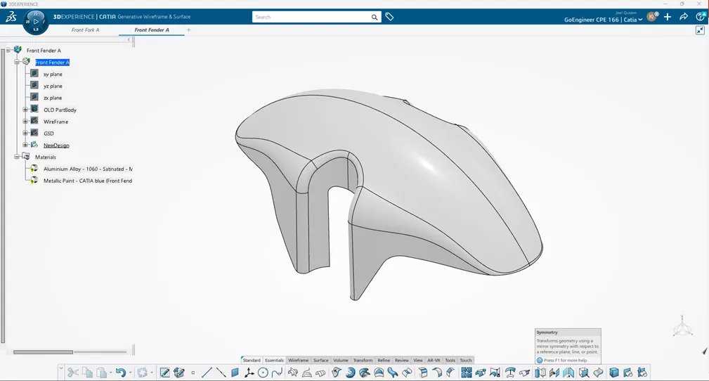
Create half the model and use the Symmetry command
Sheet Metal Design
Another powerful app within 3DEXPERIENCE CATIA is the Sheet Metal tool, which helps users quickly develop sheet metal parts with standard features.
After defining the default parameters of a sheet metal component, you are ready to go. With walls, rolled walls, bends, flanges, stiffeners, louvers, and more, users can quickly and easily model their sheet metal parts. Additionally, you can unfold the model to ensure it is manufacturable, then export a DXF file to send to your cutter.
The sheet metal order process function allows you to automatically create the models of the manufacturing steps to create the model.
These separate bodies show the model in the state from flat to fully bent.
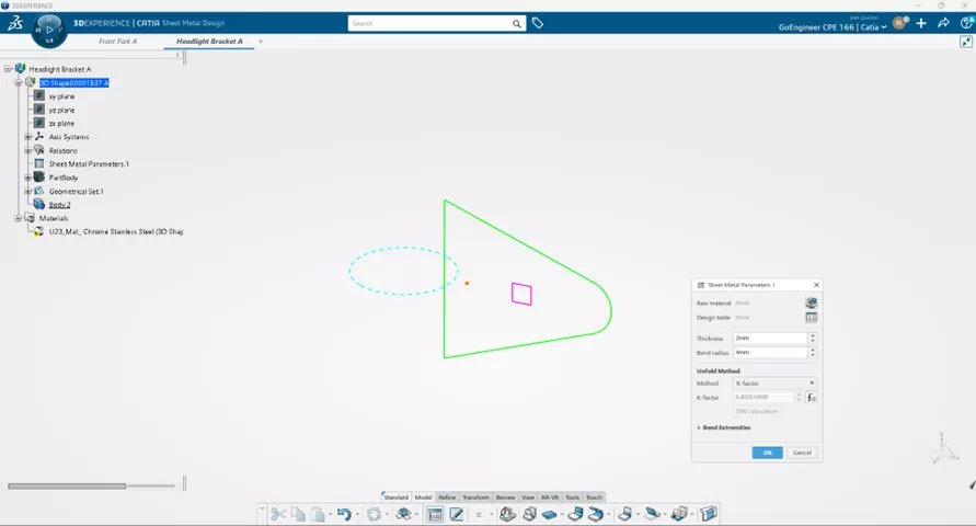
Sheet metal properties definition
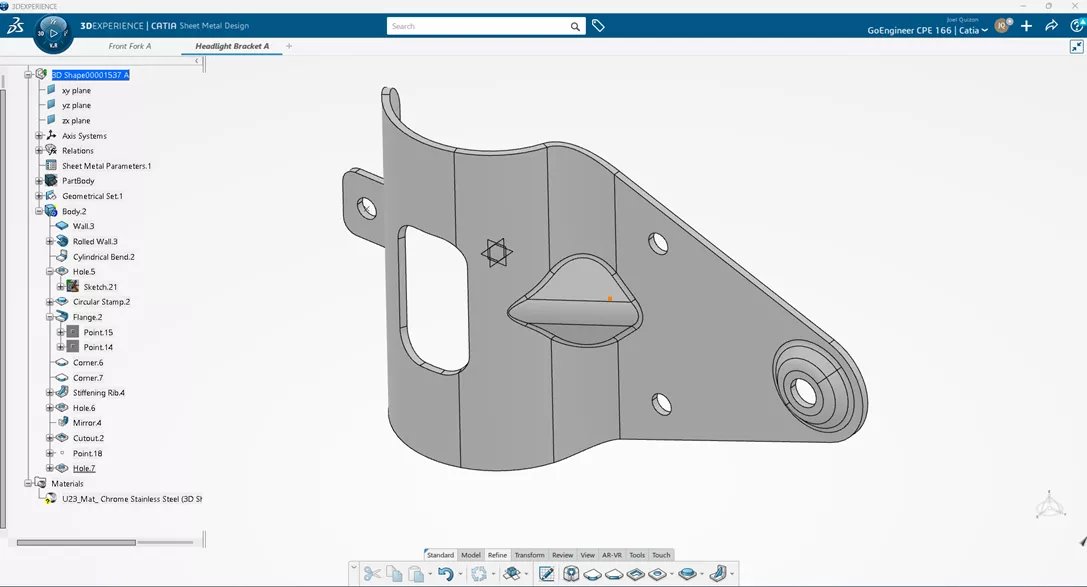
Quickly unfold model to check validity
Drawing Creation
Drawing/Drafting offers a range of familiar tools that allow you to lay out the necessary views for dimensioning and annotating. You also have the option to customize templates according to company standards and even establish business rules for designers to adhere to. For sheet metal drawings, a flat view can be easily created, and by utilizing the sheet metal Order Process command, views of the steps can be automatically generated on additional sheets, including bending and punching information.
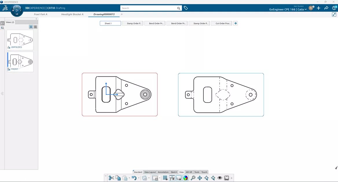
Quick front view and flat pattern view creation
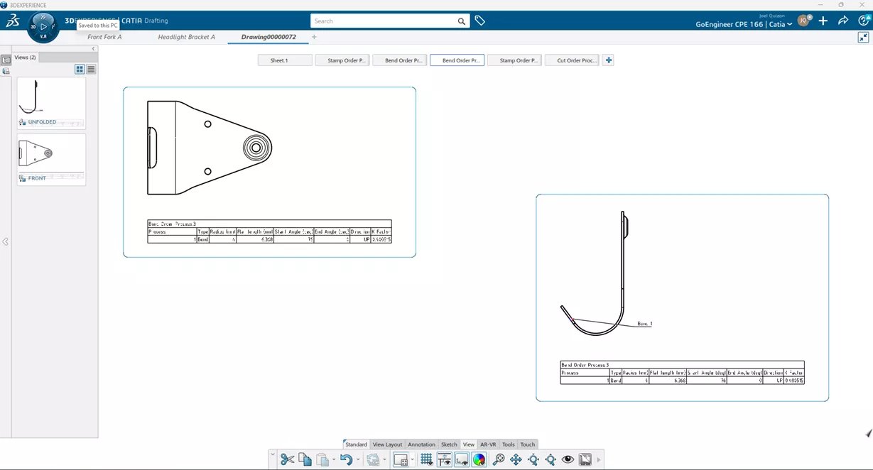
Automatic creation of sheet metal process steps on additional sheets
Assembly Design
3DEXPERIENCE CATIA assembly truly shines with its ability to efficiently work with very large assemblies and is another reason why transportation, aerospace, and marine industries choose CATIA. Constraints, mechanical mates, collision detection, and more are available to effectively create assemblies.
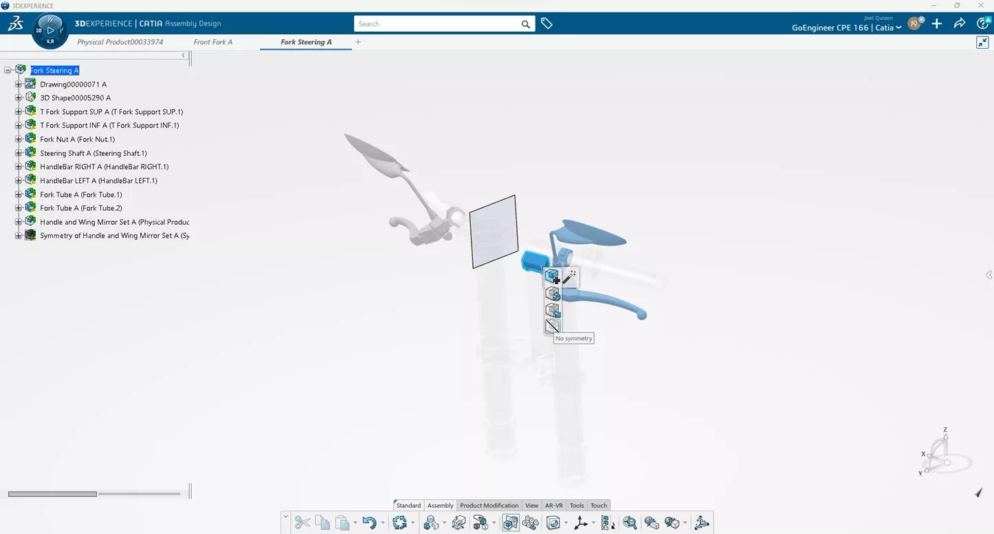
The Symmetry command is a powerful tool that lets users quickly model the other half of an assembly. Hitting the Shift key while selecting a part allows you to show the levels of that component and which assembly level you want to select. After selecting the appropriate mirroring plane, there are tools to either use existing reference, replace reference, or remove the component. It really makes the mirroring process easy.
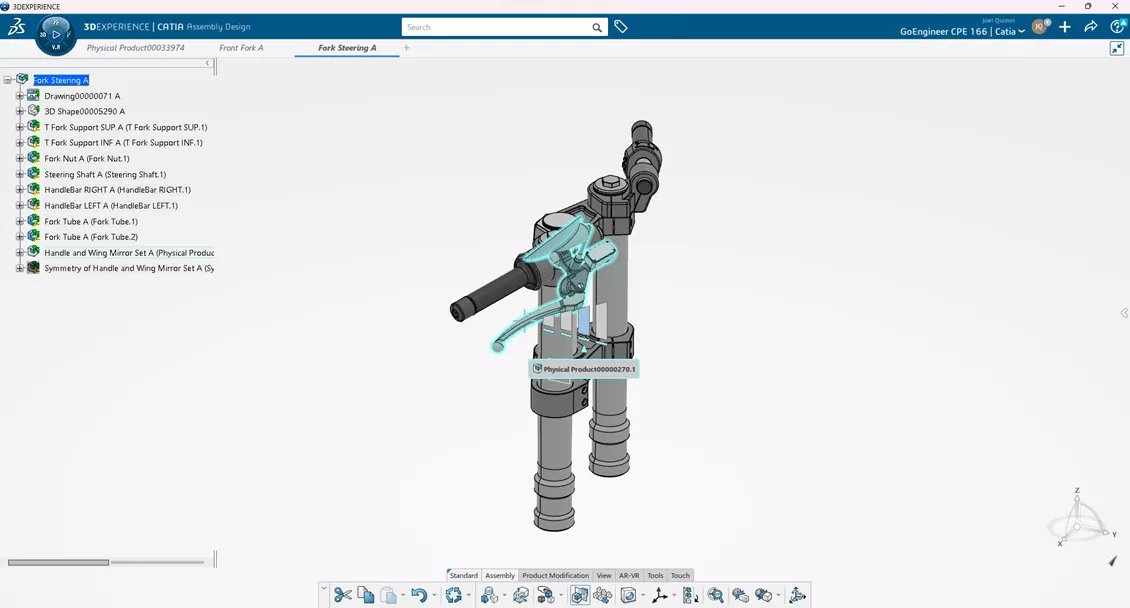
Shift key while selecting a component allows you to select appropriate level of assembly to pick
