In SOLIDWORKS, Direct Editing tools provide the flexibility to modify geometry that does not contain model features, such as an imported STEP, Parasolid, or IGES file. In this guide, we will look at some Direct Editing tools such as Move and Delete Face.
Turn on Direct Editing in SOLIDWORKS
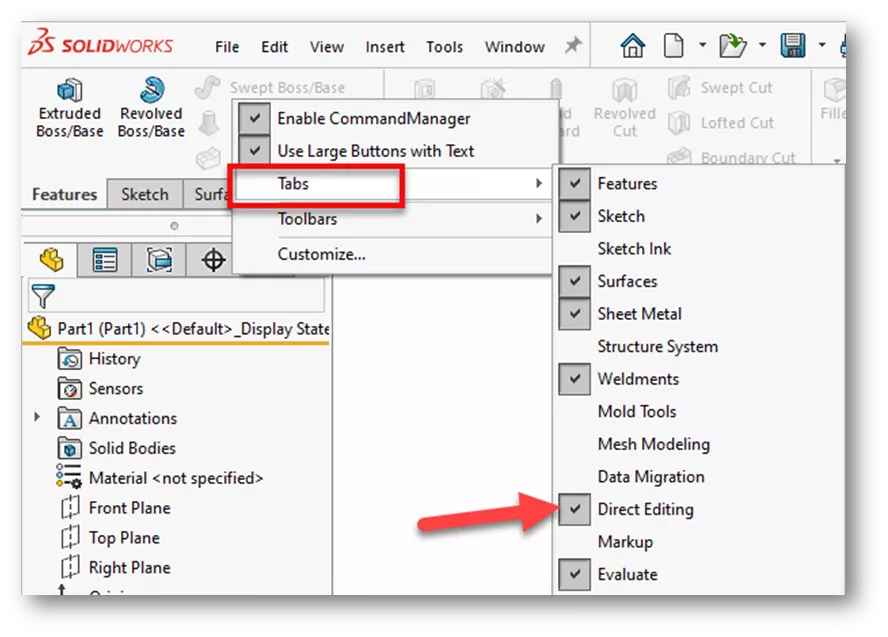
To turn on the Direct Editing tab, right-click anywhere on the CommandManager, go to Tabs, then select Direct Editing.
Move Face
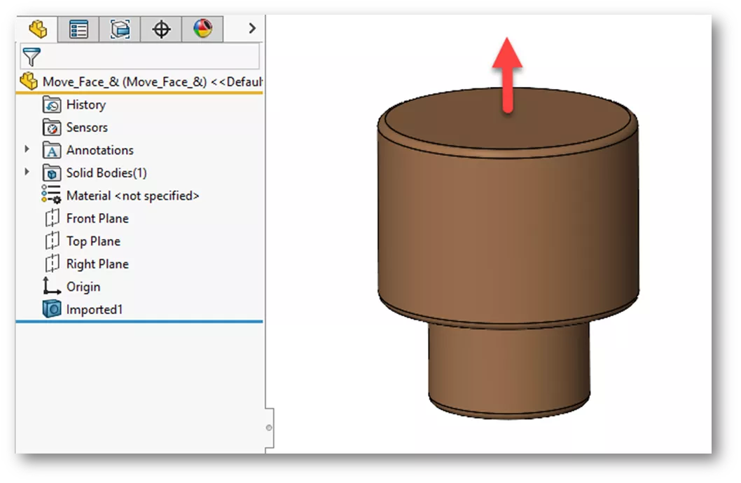
In the example below, we have an imported Parasolid with no features to edit. We need to lengthen the body in the Y-direction by 5mm. We can use the Move Face command to accomplish this.
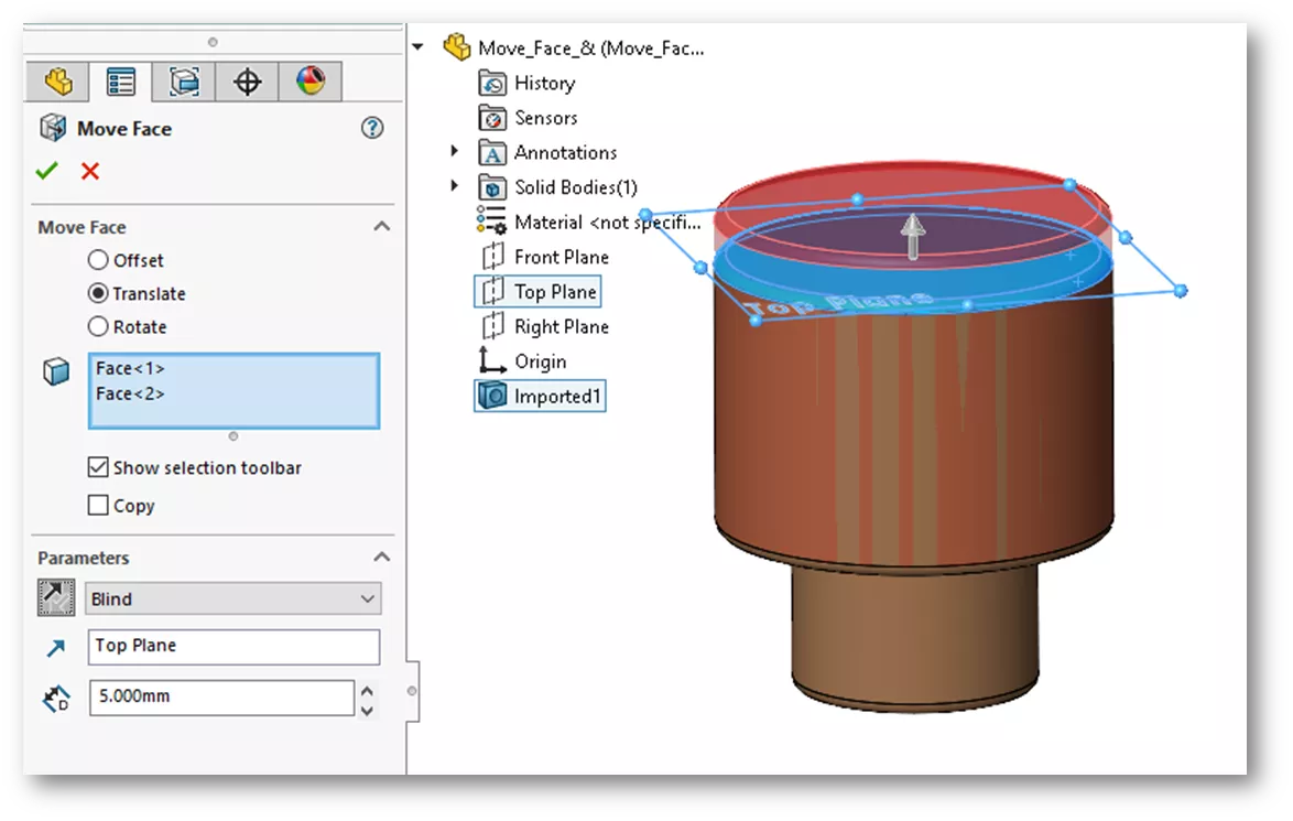
On the Direct Editing tab, choose Move Face, then select Translate. For the faces to select, here we’ll choose the bottom and filleted face of the base. Under Parameters, choose a Blind end condition, select the top plane for the direction reference, then key in 5mm for length and click OK.
Now, we need to increase the diameter of the base just a bit. We can also use Move Face to accomplish this. For this example, we will use the Offset option.Select the cylindrical face, key in a length of 3mm and click OK.
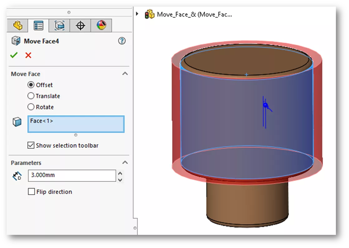
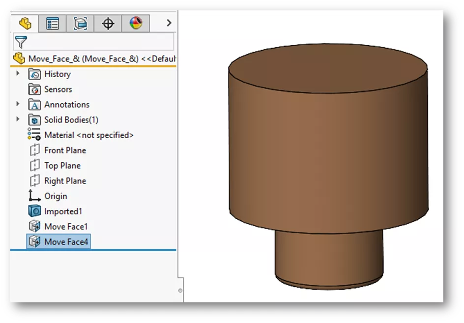
This process removes the fillets from the cylinder edges. We can add fillets or chamfers back in later.
Delete Face
Suppose we want to remove the remaining fillet and add chamfers to the edges. To remove the fillet, use the Delete Face command on the Directing Editing tab. Under Selections, choose the fillet face. Under Options, select Delete and Patch and click OK.
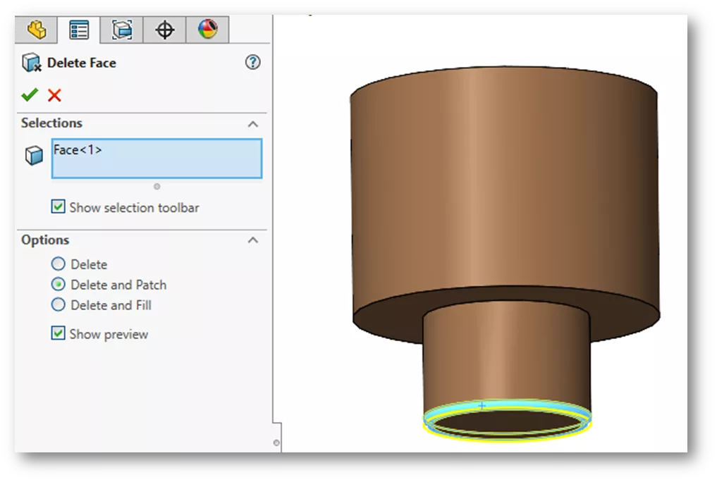
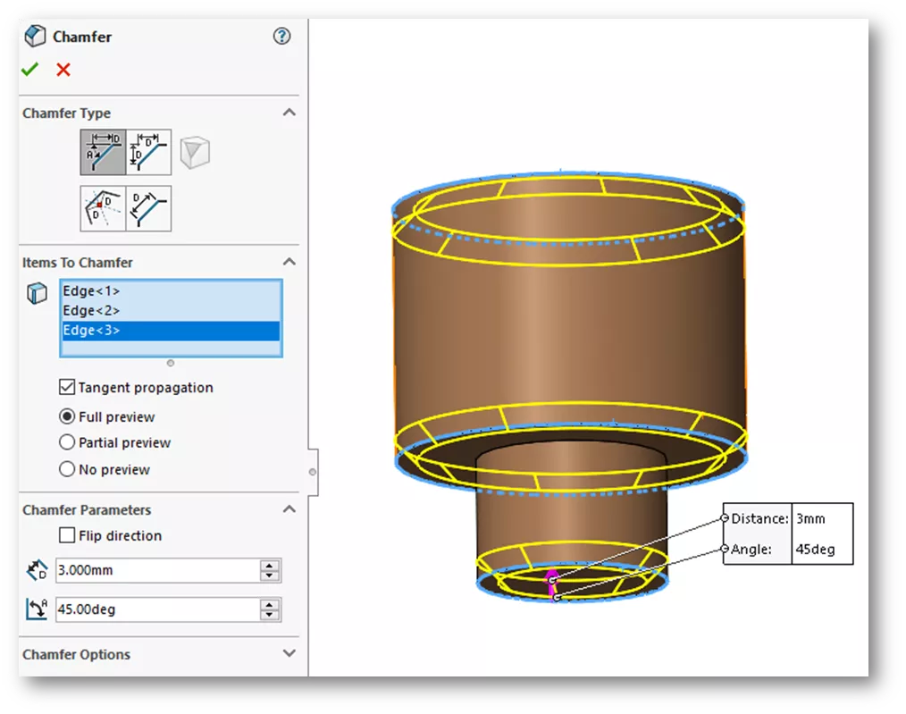
The Delete and Patch option resulted in the filleted face being removed and the edges brought together. The Chamfer command is also on the Directing Editing tab. We’ll engage the command and select the edges, key in a value of 3mm, and click OK.
