In this SOLIDWORKS tutorial, we demonstrate how to create indents at the assembly level. In this example, we have an assembly of a plate and three pieces that intersect with the plate.
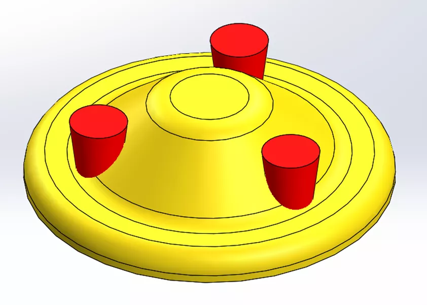
The goal is to change the geometry of the plate to encompass the three pieces on the bottom.
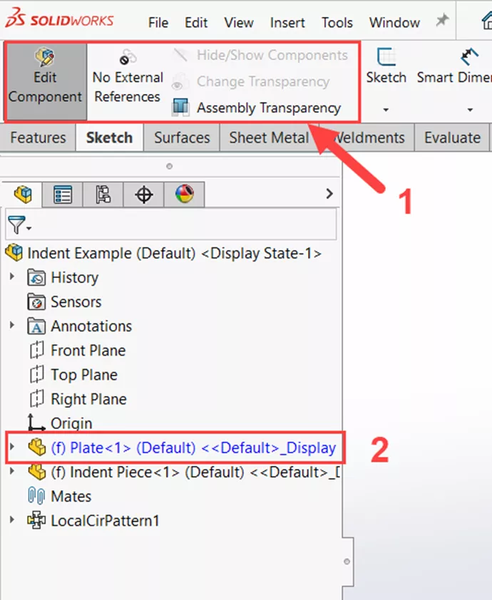
To do this, we’ll use the Indent feature. Start by editing the plate part in the context of the assembly by right-clicking on the part and selecting the Edit Part icon.
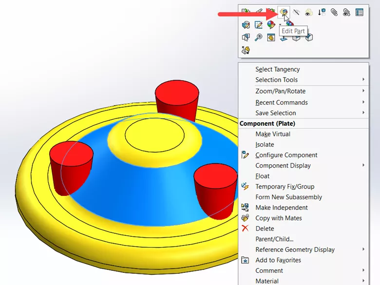
This gives us access to the standard CommandManager typically seen in part modeling. You can tell we are editing a component by the icons on the left of any tab in the CommandManager (1), and we can see which part is being edited by its blue text in the FeatureManager Design Tree (2).
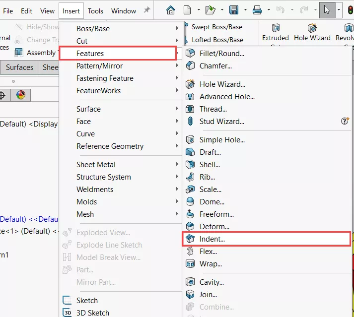
Start the Indent command by going to Insert > Features > Indent…
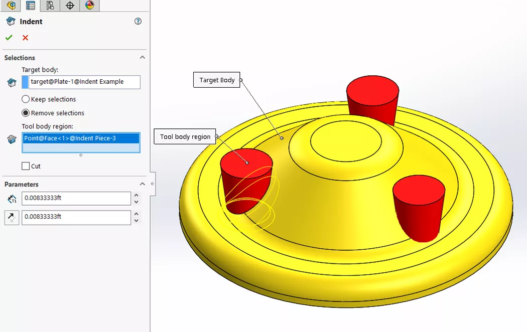
In the Target body region, select the plate and choose Remove selections. Then, under Tool body region, we’ll select one of the pieces we would like indented in the plate. Keep in mind that the Indent feature will need to be performed separately for each part; we won’t be able to select all three in one feature when working in a top-down assembly model.
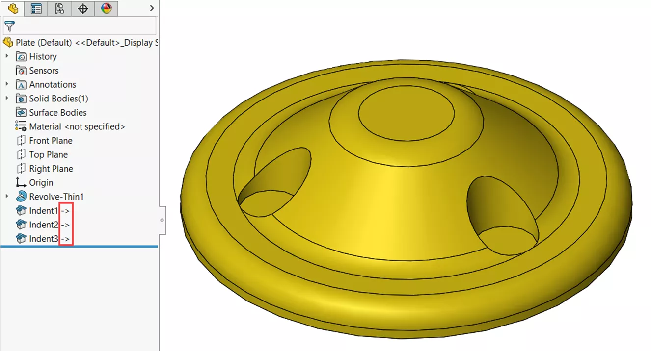
Once complete, we can exit Edit Component and open up the plate part separately to check that the features are appearing on the part file.
We can tell it is linked by the carrots next to each of the indent features in the FeatureManager Design Tree.