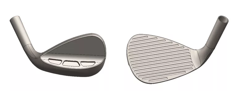
Reverse engineering is a useful approach for creating customized sports equipment and tailoring products to athletes’ specific needs and preferences. For example, running socks for an Olympic runner where extra attention needs to be placed on padding under pressure points or custom grips for a tennis racket used during Wimbledon. Even customized weight distribution and curvature of a golf club during the PGA Tour could be the competitive edge an athlete needs. In this article, we discuss a few engineering tools and the reverse engineering workflow to quickly create customized sporting equipment.
Creaform 3D scanners can be used for reverse engineering, inspection, and even 3D scan to 3D print. Specifically, the GoSCAN! Spark leveraged for 3D scanning during the workflow covered in this article.
In this example, we have a standard wedge purchased over the counter at a sporting goods store, in which an athlete would like to customize the curvature and weight distribution to their preference.

Typically, at this point in the process, an athlete would take their club to a specialist who would hand grind the camber and sole width to create a more effective bounce angle and weight distribution.
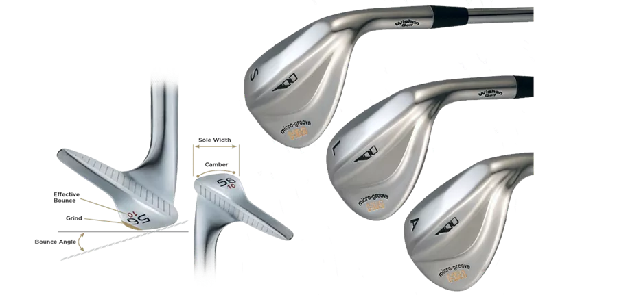
This works perfectly if only one club should be customized. However, in the professional world, athletes often create multiple sets of customized sporting equipment. Thus, we need to create a very accurate repeatable process. This is where 3D scanning and reverse engineering are used to capture the handcrafted prototype for reproduction.
Below is a scan of a custom-finished golf wedge.

Note: Creating this wedge in CAD software may seem simple but can quickly become complex given the unique geometry. GoEngineer’s SOLIDWORKS Advanced Part Modeling training course discusses using Loft and Boundary features with start and end constraints to model this wedge from scratch. But since this wedge has a custom profile made special for the Athlete, we will continue with our reverse engineering workflow.
The first step is to extract the silhouette and cross-section of the face for a 2D sketch. To do so, we’ll use VXmodel, a reverse engineering software from Creaform.
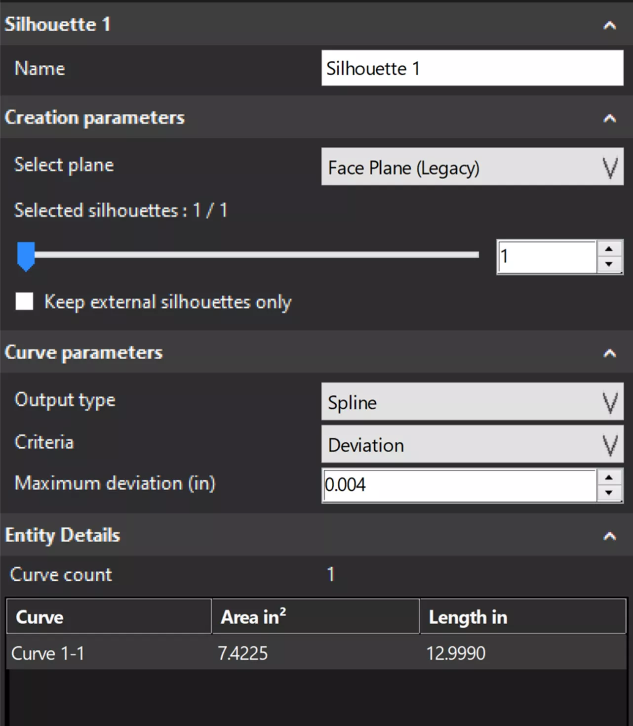
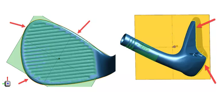
Next, we’ll extract a cylinder from the shaft.
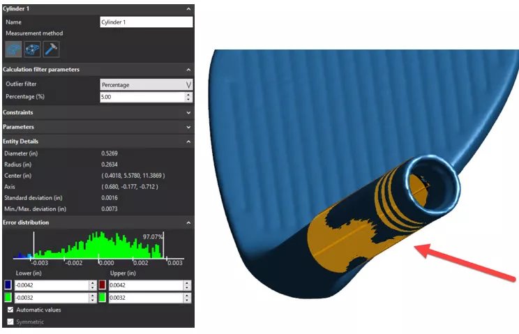
The following few steps happen in SOLIDWORKS (a simple extrude and cut), but first, we must send the information from VXmodel to SOLIDWORKS.
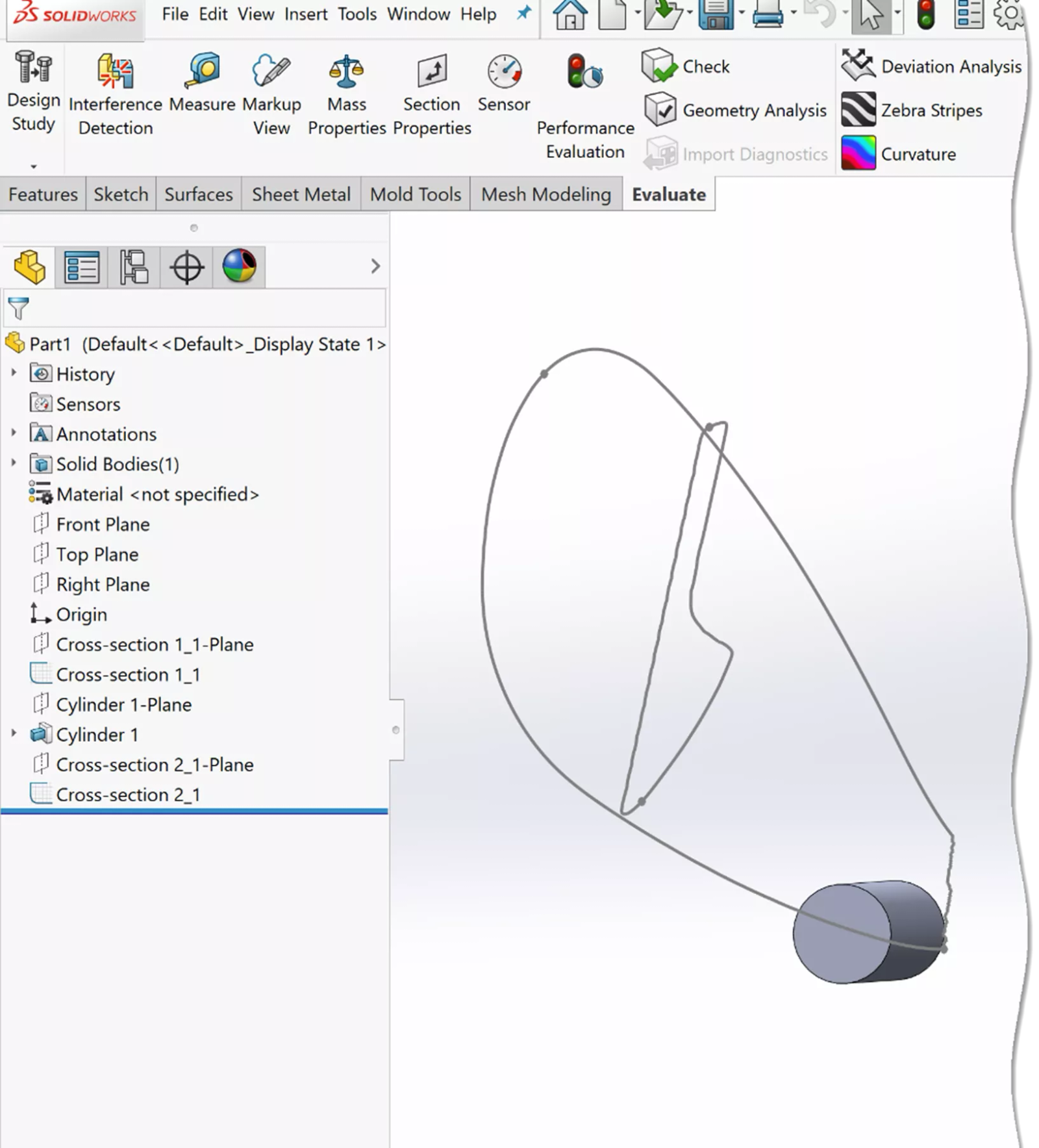
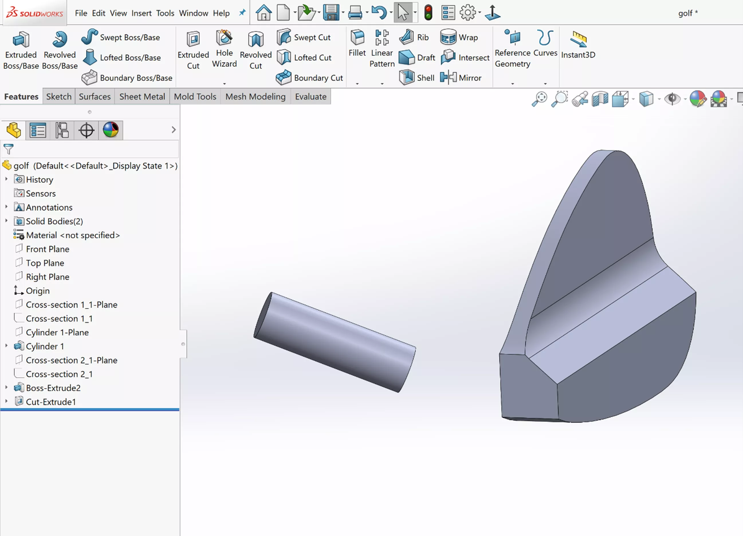
Now that our silhouette, cross-section, and cylinder are in SOLIDWORKS, we can make an extrude and cut.
The next step is critical for the customization of the wedge. We need to extract a curved surface from the wedge using VXmodel surfacing tools.
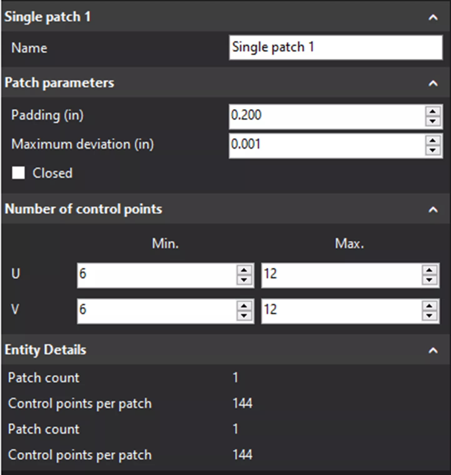
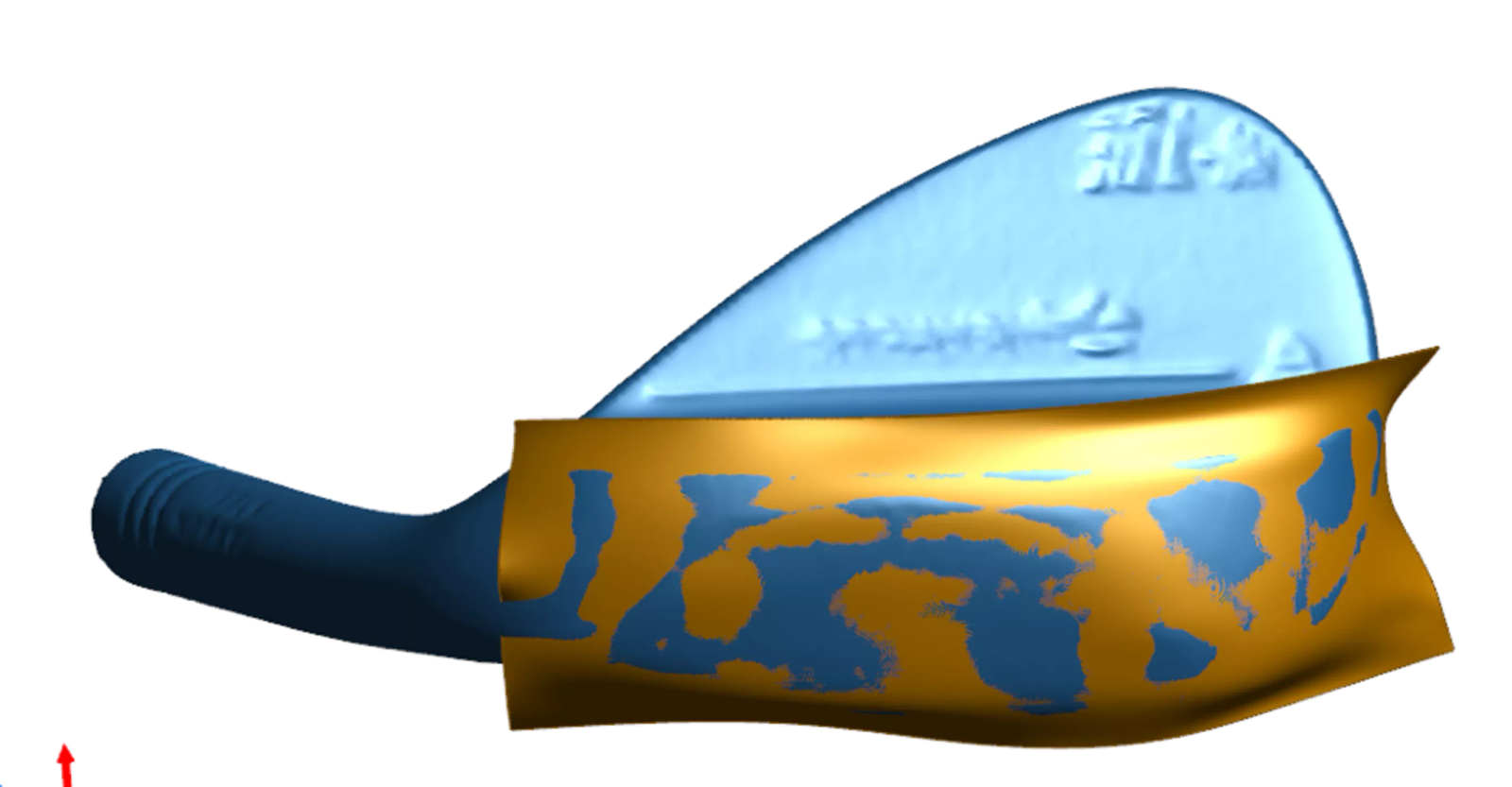
This unique tool creates a surface that follows the contour of the machined profile to match it at a high degree of accuracy.

Finally, within about 30 minutes, we have a finished CAD model for production.
