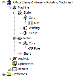
Axial Flux Motors have become very popular because of their higher power density compared to conventional Radial Flux Motors of the same weight and are very efficient and cost effective in electric vehicle and aerial applications. Power density is the ratio of output power to volume of the machine. For a given size machine Axial Flux motors deliver more torque and power, or Radial Flux motors are larger for a given power output. In this blog I provide an introduction to Ansys Maxwell’s capability to model a design and obtain FEA results. The model can be developed from nothing, or RMxprt can be used to initialize the design process (automate the geometry and excitation circuit creation.
ANSYS MAXWELL 3D
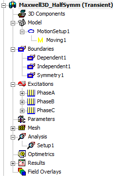
The design and modelling process consists at a minimum of setting up the motion, boundaries, excitations, mesh operations, analysis. Parameters (EM torque and force on objects) and Optimetrics (optimization analysis) are optional settings. Post processing can be setup before or after obtaining results.
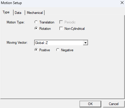
Motion
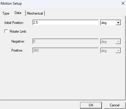
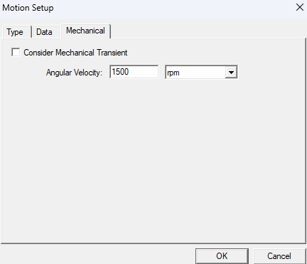
Define the rotation direction, speed, and mechanical transients (optional).

Boundaries
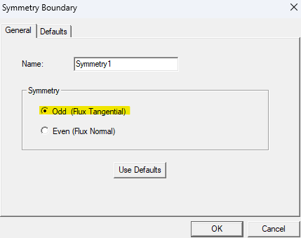
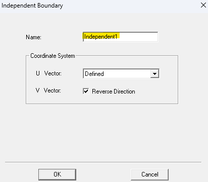
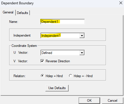
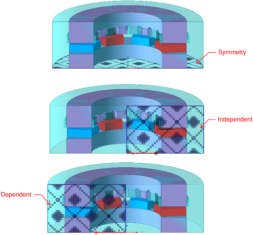
Apply rotational and planar (mirror) symmetry to reduce the model size and simulation time. It takes 28 min of simulation time to simulate a half symmetry model and 17 min of simulation time to simulate a quarter symmetry model. The simulations are run for one cycle over which steady steady is reached.


Excitations
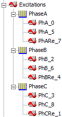
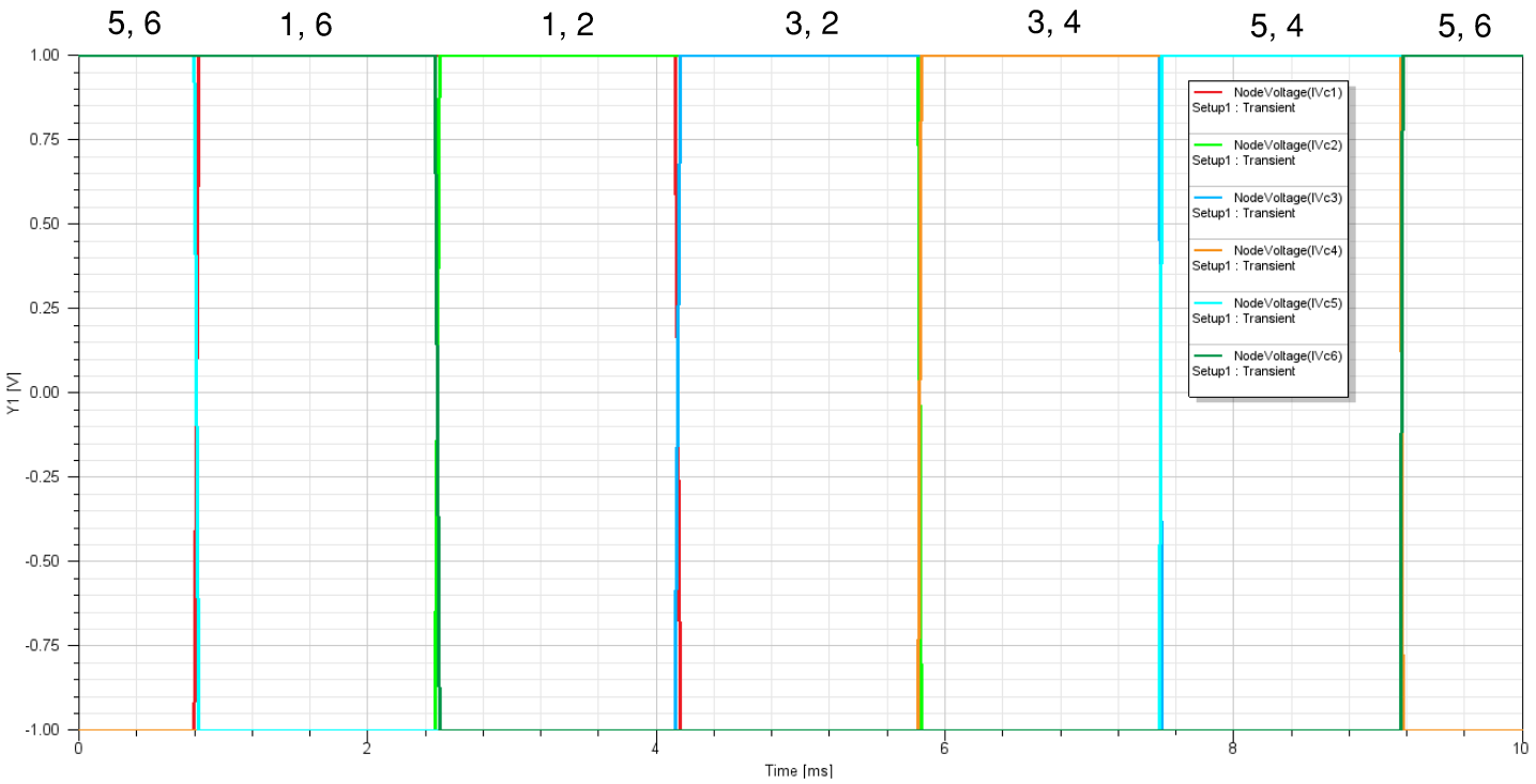
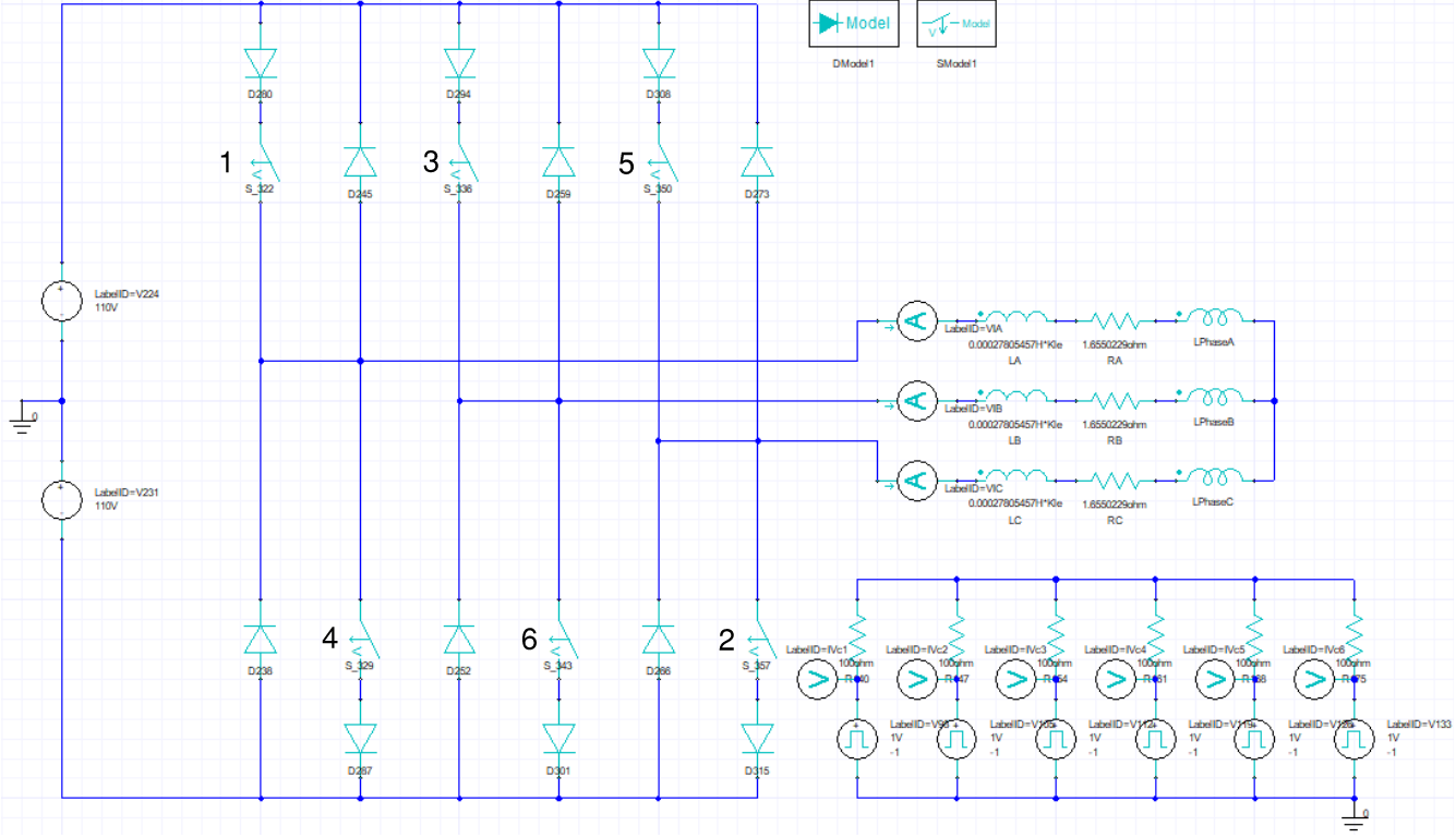
Use an external circuit to invert DC voltage excitation to three phase voltages. Switch controls can be TIME, POSITION, or SPEED based.
MESH
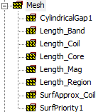
Apply mesh operations for the different type of geometry objects. The SurfApprox_Coil operation is applied to mesh the curvature of the coils, and the SurfPriority1 operation is used to prioritize the meshing of the surface of the coils.
Analysis Setup
Define the stop (simulation) time and time step and select to save field results for every time step. Also, the Calculator in Field Overlays can be used to create user defined named expressions and applied in the setup to be used to create 1D plots.
Results (Post Processing)
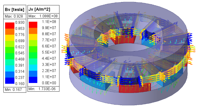
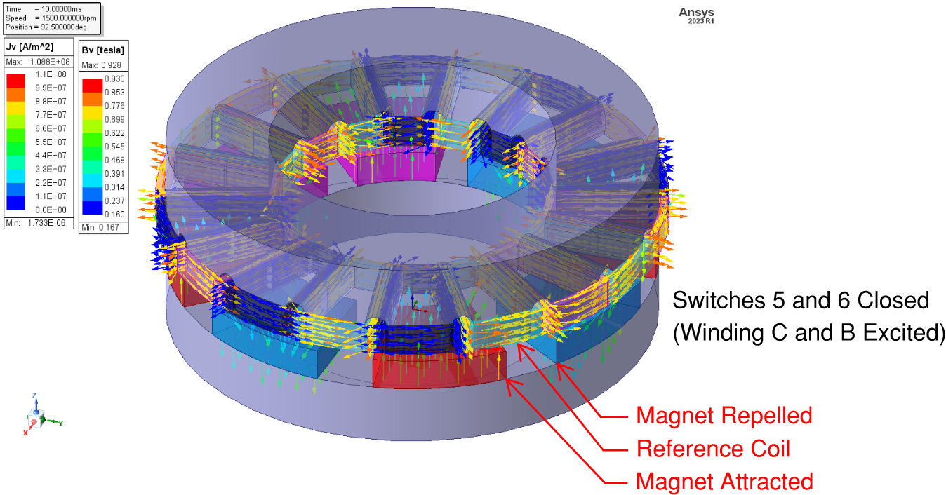
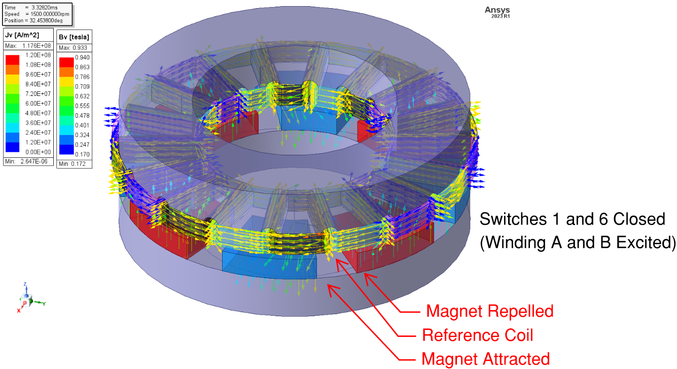
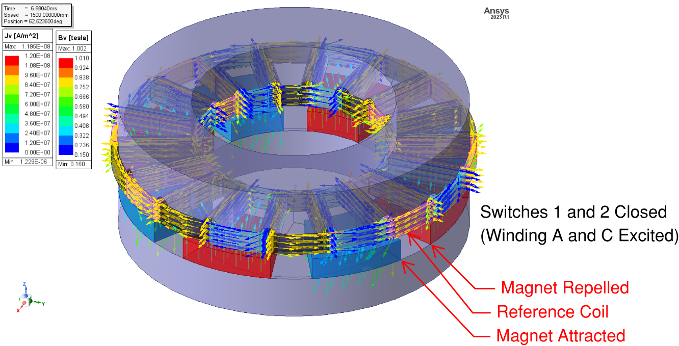
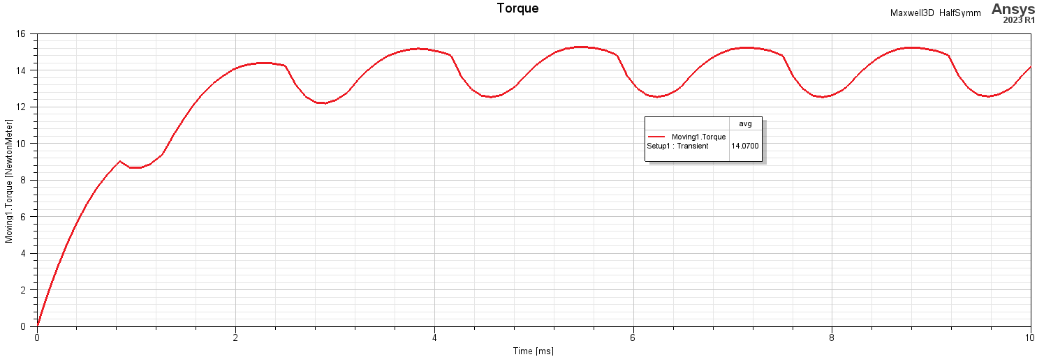
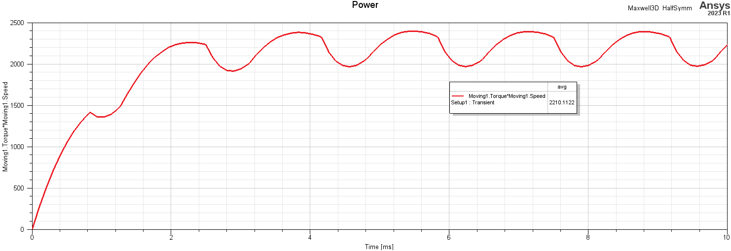
Create field plots of the magnetic flux density and winding current density. The right hand rule for EM force and torque on the stator windings can be used to determine the mechanical force and torque on the rotor magnets. The EM force and torque on the stator windings are equal and opposite to the mechanical force and torque on the rotor magnets. Produce 1D transient plots for the rotor torque and output power.

RMxprt
The initial FEA Model setup and creation in Ansys Maxwell can be automated with easy to use RMxprt templates, and the FEA model can easily modified as desired using the Ansys Maxwell CAD operations and the Maxwell circuit design.
