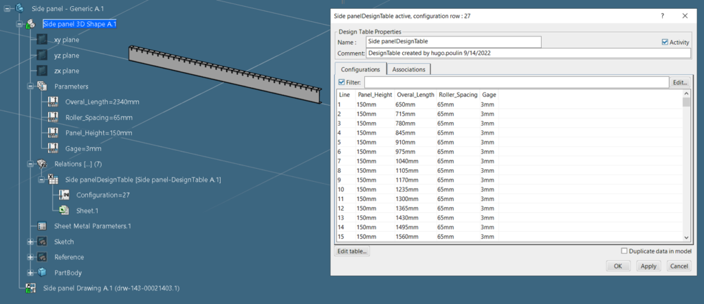
For some, the idea of designing products with an Excel spreadsheet may seem far-fetched. How can a spreadsheet have anything to do with the design process? A spreadsheet contains only rows and columns of data, right? There is no doubt that spreadsheet data will never replace feature-based geometric modeling. However, a spreadsheet can perfectly complement the parameterization of a part model where several configurations are anticipated.
In this blog, we will explore the different Dassault Systèmes 3DEXPERIENCE platform solutions that use a spreadsheet to simplify the creation and management of a group of similar parts, commonly called a component family. More specifically, we will illustrate how to use the Design Table, Component Family, and Product Table tools and examine the benefits they can bring to your processes.
Reduce and Eliminate Tasks that Have No Value
In many industries, design reuse and standardization play an important role in the productivity and profitability of projects. The goal is to use as many proven design concepts as possible to meet the needs of the new project underway. This reduces the effort required from the product design team in addition to mitigating manufacturing risks. This way, we are not reinventing the wheel.
Take for example the case of a company that manufactures roller conveyors. To meet the varying needs of the market, this company must be able to produce a multitude of different conveyors. Depending on the products to be conveyed and the plant layout, several characteristics may differ from one project to another. Here are some examples of variable characteristics: the length, height and width of the conveyor, the type of rollers and their spacing, etc. There is an array of options that may need to be changed from project to project. Having a designer manage these changes by altering part geometry is not a value-added task.
For the majority, the idea of redoing design work to create similar products will seem like a chore they would rather do without. In addition, if the company has a rigorous release process where each part is validated by the methods department, the redundancy of similar parts will be perceived as a waste of time. No need to elaborate further to understand the potential negative impacts such as frustration or disengagement that some employees might experience.
Fortunately, the solutions offered in the 3DEXPERIENCE platform greatly facilitate the standardization and reuse of product designs. Let’s explore these solutions:
What is a Component Family?
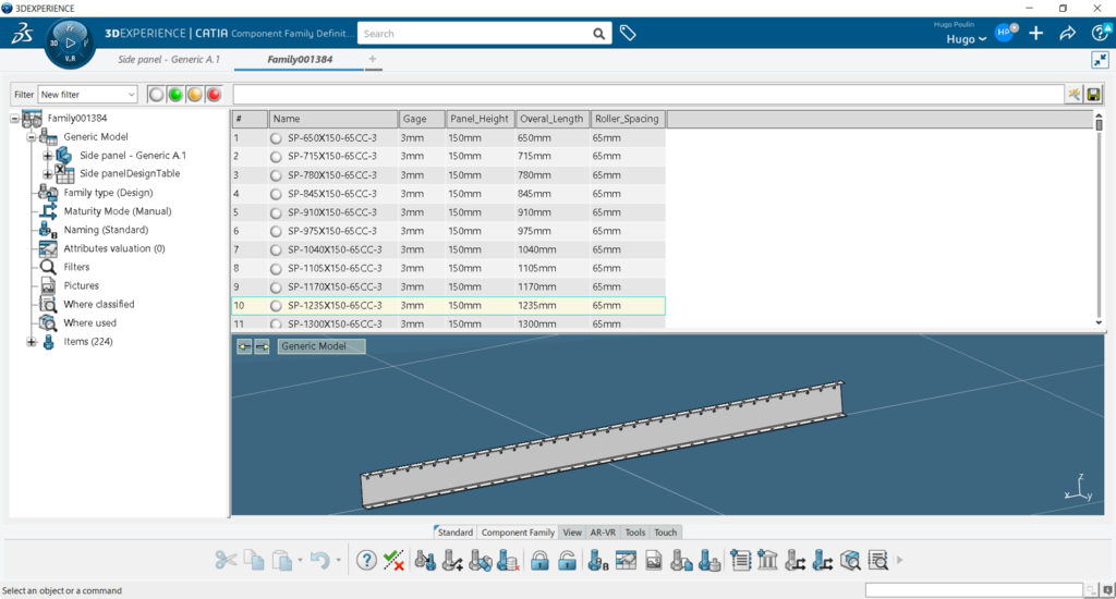
Among other things, a Component Family allows users to define and manage the variability of an in-house product. This ensures better control of standardization. The 3DEXPERIENCE CATIA Component Family Definition app offers a simple and user-friendly way to generate and manage a multitude of parts through a generic model. This generic model is defined with parameterized variable dimensions that are governed by a Design Table, an Excel spreadsheet. Each column of the table can be associated with a parameter and each row associated with a unique configuration of all the parameters. It is thus possible to create a large quantity of parts from the same document. This also reduces the effort required to maintain documentation.

How to Create a Component Family
Let’s go back to our conveyor example and explore the Component Family concept with the side panel. The first step is to design the parameterized generic model. This model should not be found in a product structure since its only use will be to generate the parts of the family. The next step is to create a Design Table to link the variable parameters to the different configurations.
There are two ways to create a Design Table: by leveraging an existing spreadsheet or creating a new spreadsheet with the current parameter values. Establishing the different configurations in Excel offers certain advantages; it is easier to manipulate the data and users can utilize the formulas to generate the cell value. Once the different configurations have been created, all you need to do is save the spreadsheet to automatically synchronize the Design Table. The part geometry is now driven by the Design Table.

At this stage, it is important to define the material in the generic model in order to assign the correct weight when solving the part family. It is also possible to attach a 2D drawing to the generic model. This drawing will be updated during the solve and all dimensions affected by the parametrization will follow. It is therefore of no value to apply fake dimensions or parametric dimensions. This is noteworthy as only one drawing is necessary to allow you to generate any number of different drawings.
It is now time to create the part’s family. To do this, simply launch the Component Family Definition application with the generic model open in session. A new Component Family PLM object will be created automatically. In the Component Family Model tab, the Family type should be set to design family. It is preferable to use the manual change option for maturity management.

The Design Table will be loaded and the Excel parameters that have not been associated with the model will also be present. These parameters can be associated with properties using the command Value Attribute. The Weight Management command allows you to automatically calculate the weight and the center of gravity of the components to be solved. To resolve the family, simply use the Test and Resolve Family Item command. The Component Family Definition app also offers tools to control changes and revisions. It is important to mention that any modification will have to be made in the generic model and then propagated to the solved models. You should never modify a resolved model directly.

