In this blog I discuss dielectric breakdown and how to use Ansys Maxwell to calculate inception and breakdown voltages. A dielectric is an electric insulating material and every dielectric has a voltage limit which if exceeded causes dielectric breakdown and electric arcing within the dielectric. Inception voltage is the voltage limit that if exceeded ionization of the dielectric begins. Breakdown voltage is the voltage limit beyond the inception voltage such that if exceed the dielectric is fully ionized and full electric arcing occurs.
MODEL
The Ansys Maxwell Electrostatic solver is used in this example. The model consists of a copper electrode at 100V potential, a copper disc at 0V, a post processing rectangle for plotting the E Field and Field Line Traces (Arc Lines), and a model region boundary not shown.

SETUP
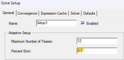
Right click on Analysis and select “Add a Solution Setup”. Right click on Setup1 and select “Analyze”.

RESULTS
Right click on the post processing rectangle and select Fields >> Emag. Next, right click on the post processing rectangle and select Fields >> Markers >> and choose “Add Markers” as many as desired and place them in locations of interest. The position of the markers may be edited. In this example five markers were selected with 1mm separation and one marker at the center of the electrode tip.

Then add a Field Line Trace, select the region volume, and select all markers that were added to the model.

The Field Line Traces (Arc Lines) are Superimposed on the Electric Field magnitude distribution over the post processing rectangle.

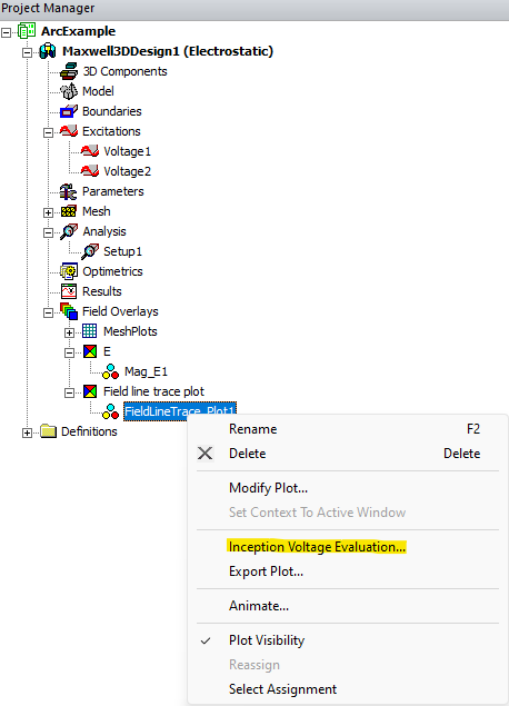
Right click on the Field Line Trace plot and choose “Inception Voltage Evaluation”.

Highlight all the rows corresponding to the markers and select “Evaluate”. Adjust the dielectric properties as needed. The streamer constant “k” depends on gas type and is a value between 0 and 1. As k approaches 1 then the Inception Voltage and Breakdown Voltage becoming closer in value.


