

Reverse Engineering Deliverables
If you need to create a digital version of a physical part, you’ll need reverse engineering service. We can create a file that’s usable for your application, however, “usable” is subjective and dependent on several factors.
During the technical call with an application engineer, they’ll talk you through the options to help determine which file is best. To get started though, ask yourself, what will you be using it for? Do you just need a file for 3D printing and/or simulation, or maybe a dumb solid that will go into an assembly to build upon, or do you need a fully editable CAD file so you can make modifications?
Below is an overview of reverse engineering deliverable files, what they are usually used for, and how they affect project cost.
STL
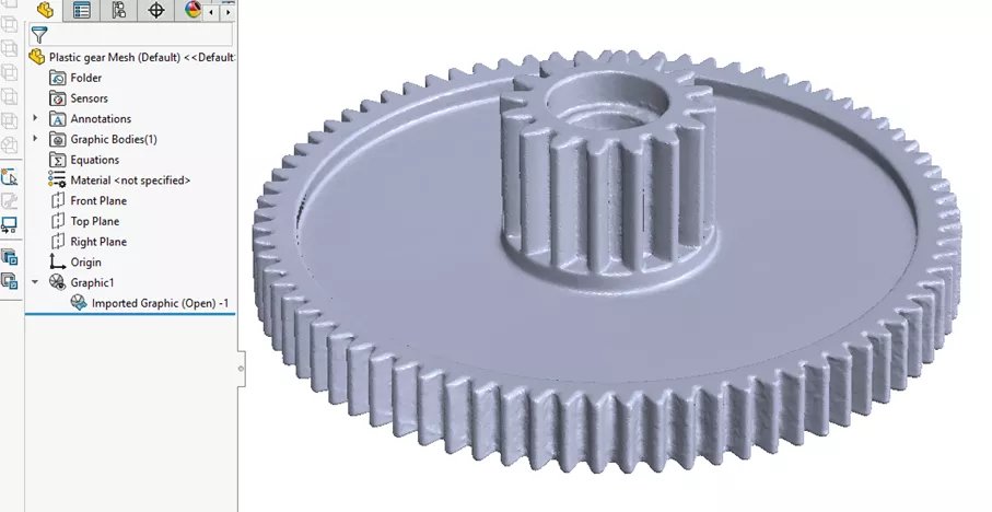
An STL file is the raw output of our 3D scanners; we record thousands of points on the surface of the part and triangulate them into a usable mesh. We then clean the data and fill in any holes to produce a manifold (“watertight”) model. STL files are popular for anyone looking to 3D print the part or use the mesh in a simulation such as FEA or CFD. However, STL files can be difficult using parametric tools like SOLIDWORKS. With only minor post-processing needed to prepare the data, this file type is the most affordable.
NURBS Autosurface
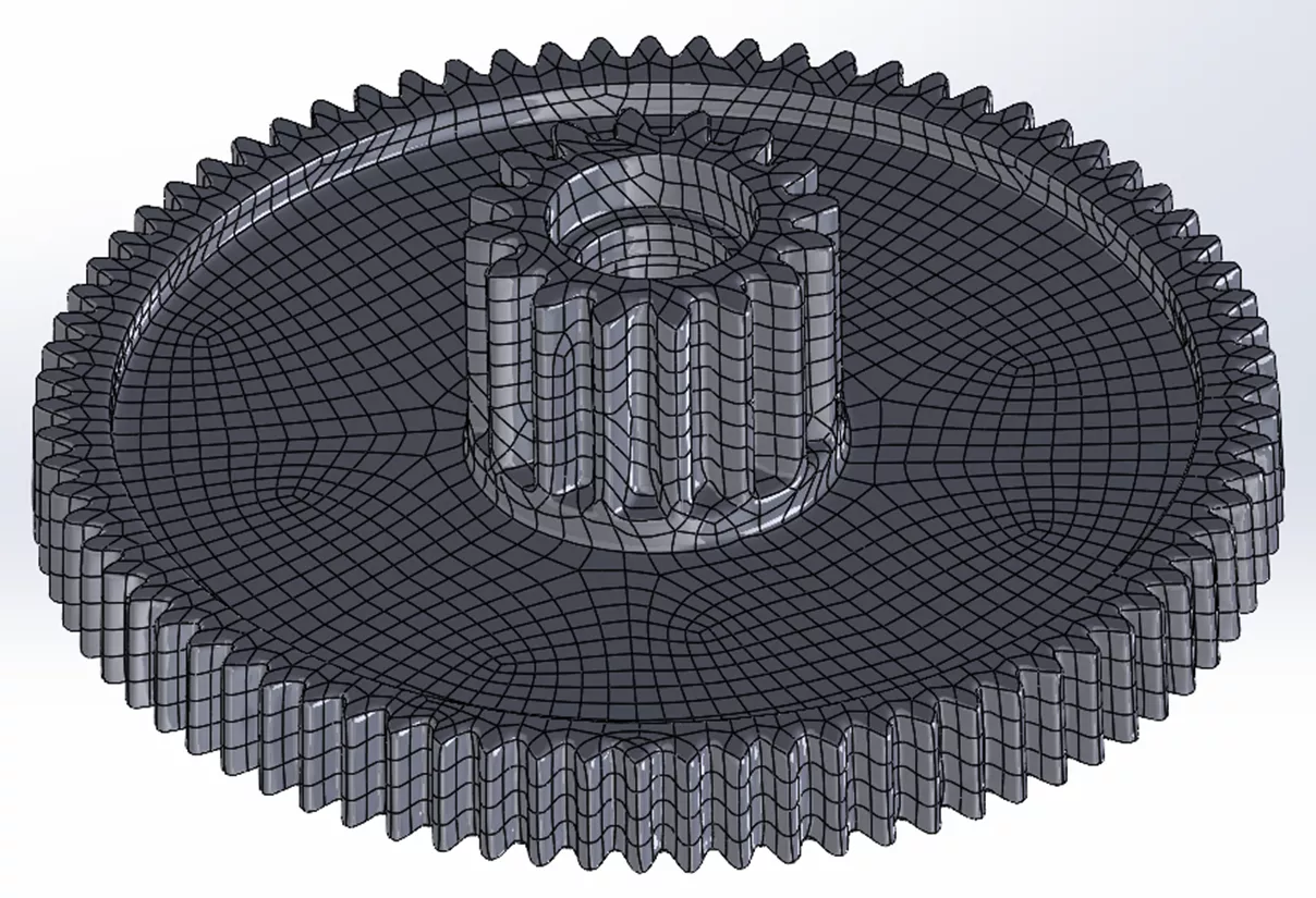
If you need a solid model to bring into SOLIDWORKS and don’t plan to use it for anything other than a fit check in your assembly, or if it is a very complex/organic shape that would take a long time to fully reverse engineer, then a NURBS autosurface (e.g., step, iges, etc.) might be the right choice.
The autosurface process accurately wraps surface patches around the scanned mesh to create a solid body. This solid body can be imported and manipulated in CAD packages more easily than STL meshes, though editing and drawings are more difficult than with parametric data.
The process for creating this file is fairly quick (inexpensive), offering more functionality than an STL without time spent creating a parametric CAD model (which is why this option is still very economical).
Hybrid Model
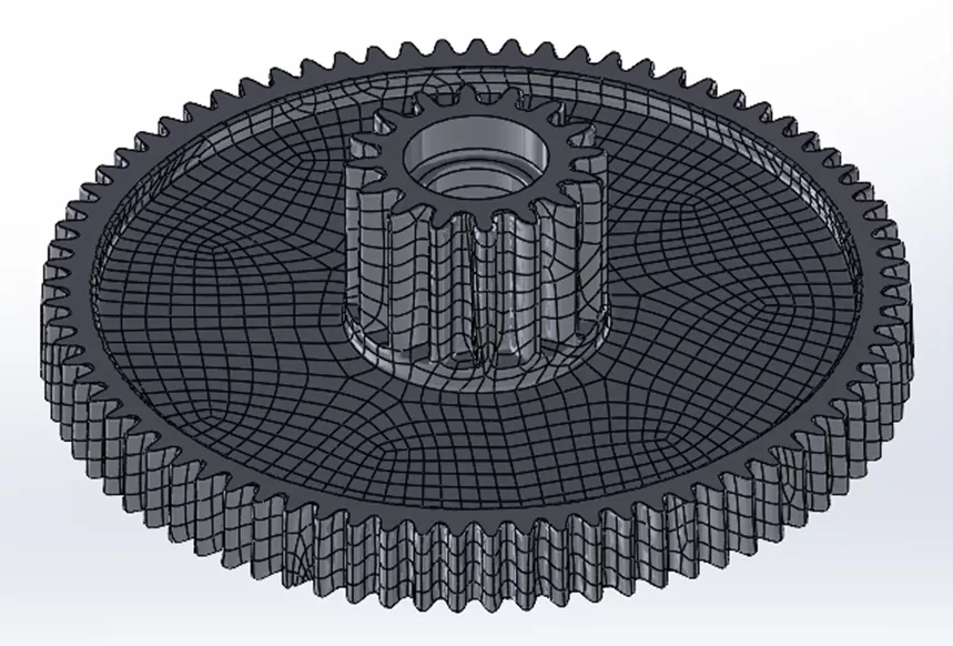
A hybrid model is a cross between a NURBS autosurface model and a geometric STEP file. Most of the part is wrapped in surface patches, but certain features are created as parametric. These features could be critical to mounting/mating in an assembly, important to function, or features you need to change or idealize.
The hybrid model approach is great for projects where you don’t need to edit every feature of the part, but do plan on editing some of them, or when planar and cylindrical surfaces are needed to mate the NURBS model in an assembly. With only a few features that need to be modeled as parametric, hybrid model projects are the best bang for your buck.
Geometric STEP
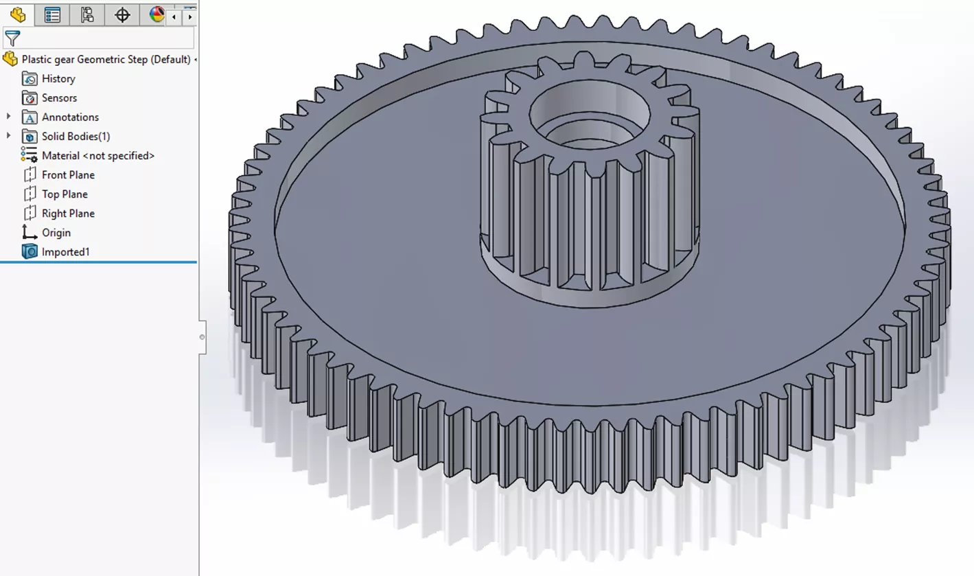
The most popular option is a Geometric STEP file. This file balances affordability with editability and is created by parametrically reverse engineering the part using the scan data as reference. It allows us to model the part with engineering design intent, idealizing features to make the model perfect. Holes are modeled as cylinders, flat surfaces are planar, and everything looks just like it would if you modeled it in SOLIDWORKS.
The Geometric STEP file deliverable is great when you need a CAD model to build on, use in an assembly, or make minor edits to. The only thing that separates the Geometric STEP file from a native CAD file is the lack of a parametric feature history (FeatureManager Design Tree in SOLIDWORKS). While slightly harder to make adjustments than native filetypes, this option is used by customers needing to document the part dimensions in an engineering drawing, make a mold or other tooling from it, or to speed up the design of parts that interface with it.
Native SOLIDWORKS (SLDPRT)
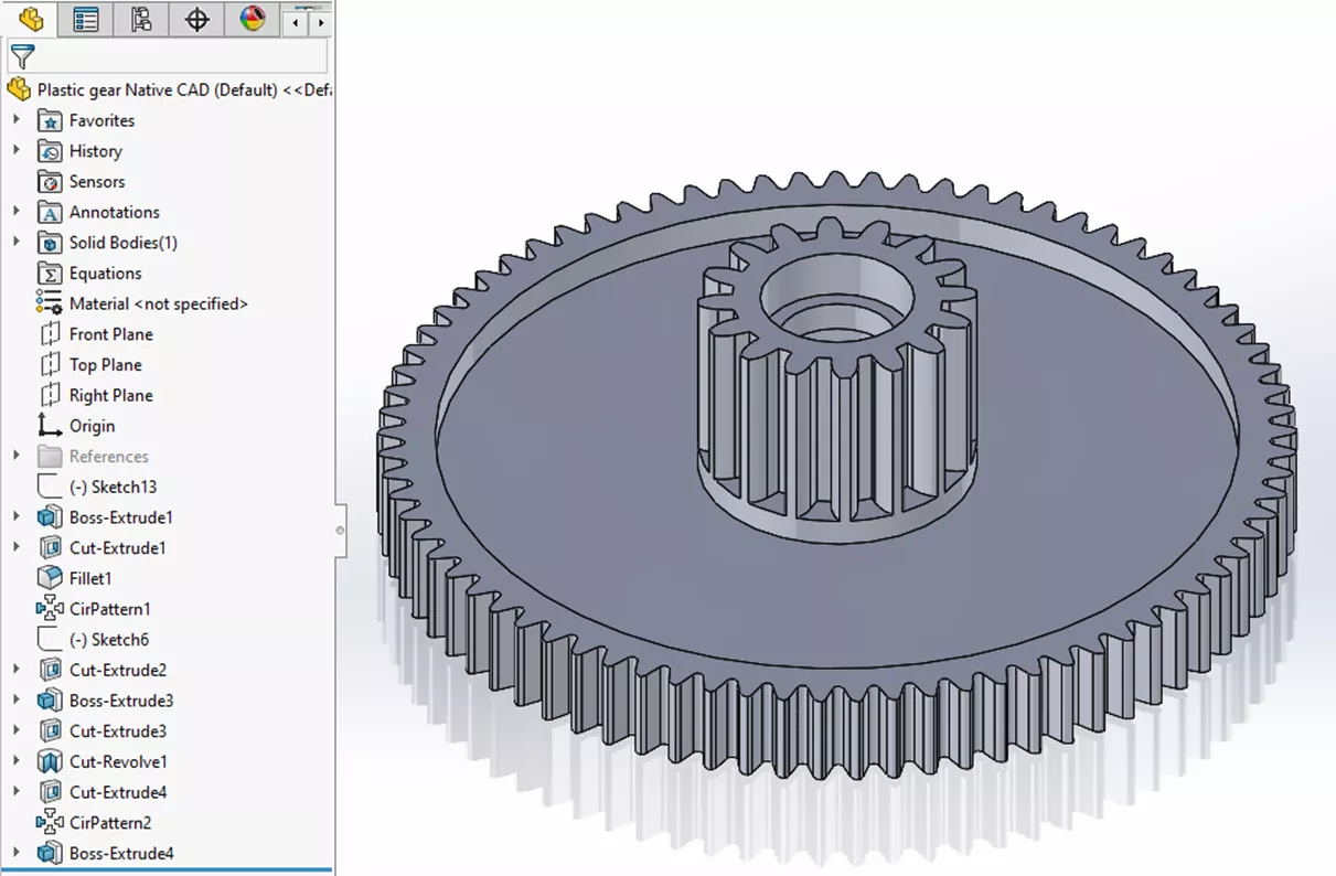
Rounding out the reverse engineering list is the gold standard in terms of functionality, complexity, and usability – a parametric SOLIDWORKS file. Like anything else modeled in SOLIDWORKS, it has parametric features with a fully defined FeatureManager Design Tree – making it editable, configurable, and suitable for any application. We work with you to ensure the file is made in the same version of SOLIDWORKS you already use, so it’s ready to drop into your workflow.
A parametric SOLIDWORKS file is the most time-consuming to create and requires expertise to give you a clean, logical feature tree; hence, why it is our most expensive deliverable.
Quality Inspection Deliverables
Quality inspection deliverables are even more bespoke than the reverse engineering projects, usually, the process requires a conversation with an application engineer to discover what your ideal inspection entails. While always being custom, there are a few tiers we can separate projects into.
Colormap Inspection
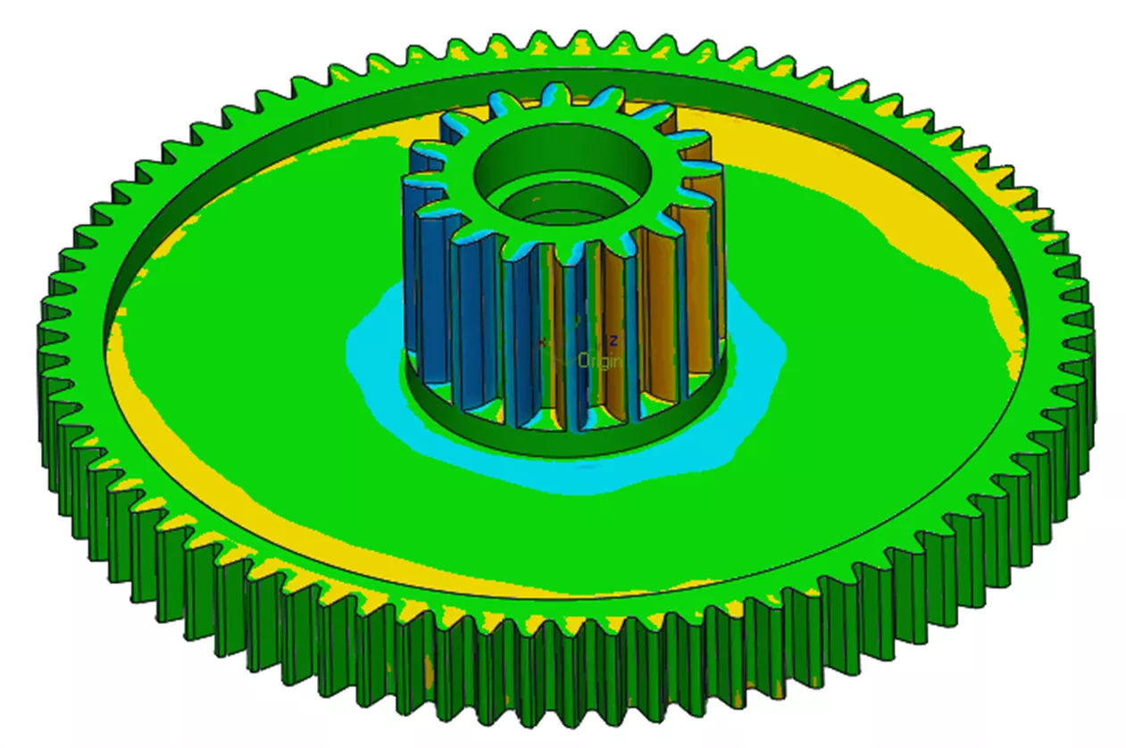
A colormap inspection is a simple analysis to compare your CAD file to the physical part(s). We overlay the two using either a ‘surface best fit alignment’, or a datum alignment of your choosing. Once aligned, we calculate the height of the surface of the part compared to the reference CAD, then translate these deviations to colors, overlaying them in the CAD for you to identify areas of non-conformance. A colormap inspection is the quickest and most affordable option we provide, offering a wealth of information about where potential problems are, and how far from nominal the deviation is.
Basic Inspection
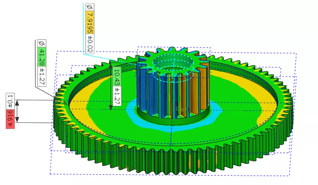
A basic inspection includes the colormap inspection along with specific dimensions that are calculated and displayed in an inspection report. For this inspection deliverable, we’ll need you to provide the CAD file and the engineering drawing for the part. If not every dimension on the drawing is critical, annotate the print so we know exactly which measurements need to be taken.
This deliverable includes a PDF report showing the colormap comparison, and then snapshot views that match up to the views on your drawing with the actual dimensions taken from the physical part. Typically, a basic inspection includes linear, radial, and angular dimensions, but does not include any advanced GD&T or damage/wear analysis.
Advanced Inspection
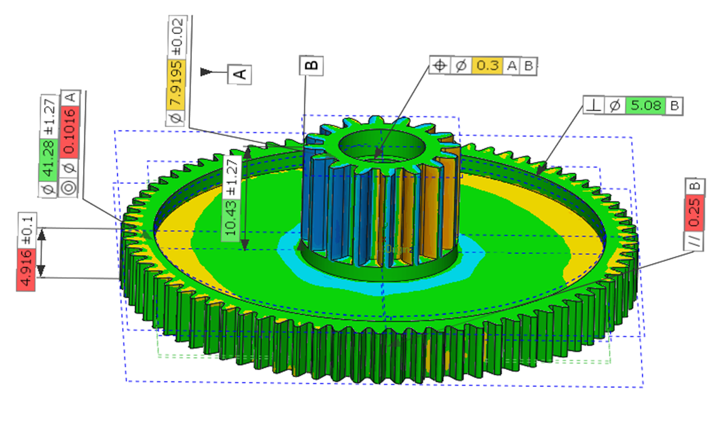
The advanced inspection goes even further into detail than the basic inspection, including everything already listed above plus everything else you might require from an inspection: GD&T, damage/wear analysis, airfoil analysis, and more. If you also have a high volume of parts, we can create batch inspection programs to keep up with the demand and then use that data to analyze trends or possible problems in your manufacturing process.