

The SOLIDWORKS “Split” command (Insert > Features > Split) is a great tool for breaking a solid body into multiple sections and/or deleting sections of a solid body or bodies. This blog will review this tool and help you better understand the resulting bodies.
The Split command is split into three primary areas:
- Trim Tools
- Target Bodies
- Resulting Bodies
Trim Tools
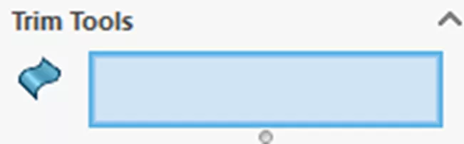
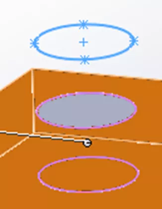
The Trim Tools are the geometry that will intersect and cut the desired solid bodies. There are two behaviors based on the type of trimming tool you select.
- No extension – Trimming body must completely intersect the body to cut.
- Infinite extension – Automatically extends the trimming body infinitely.
No extension geometry includes:
-
- Surface bodies

- Surface bodies
-
- Non-planar faces from a solid body
- Non-planar faces from a solid body
Infinite extension geometry includes:
-
- Reference Planes
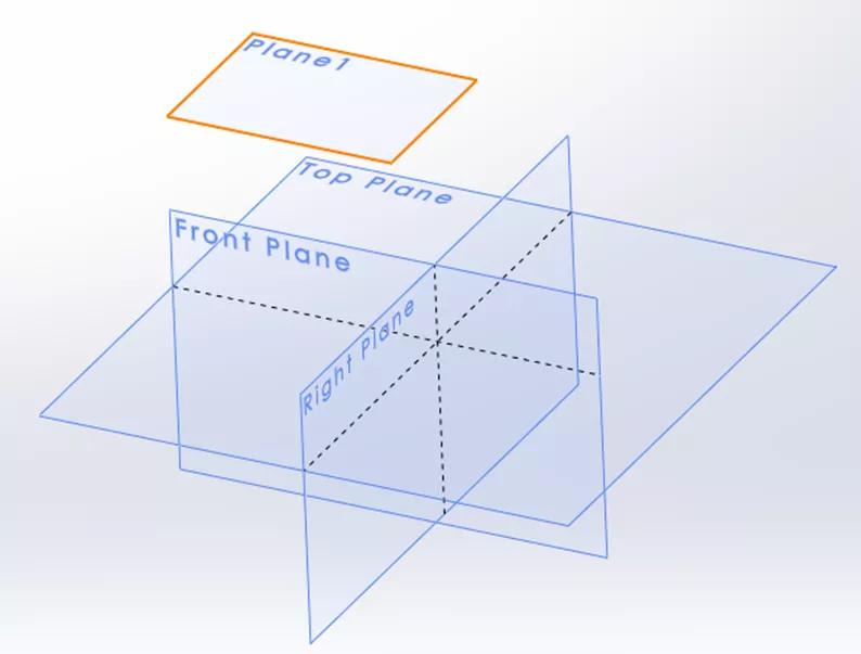
- Reference Planes
-
- Planar model faces (selecting a planar face directly from a solid body)
- Planar model faces (selecting a planar face directly from a solid body)
-
- Sketches (extension direction is perpendicular to the sketch plane)
- Sketches (extension direction is perpendicular to the sketch plane)
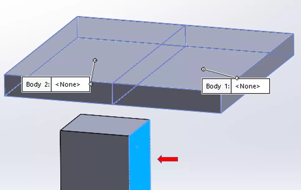
Target Bodies
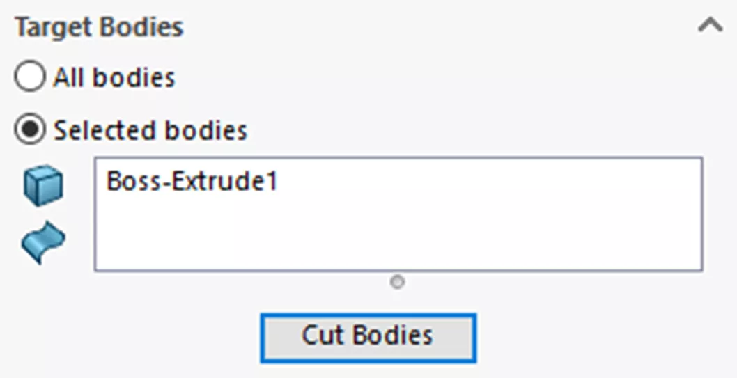
Target Bodies are the bodies to be split. You can split All Bodies or Selected Bodies.
Click Cut Bodies to create the split.
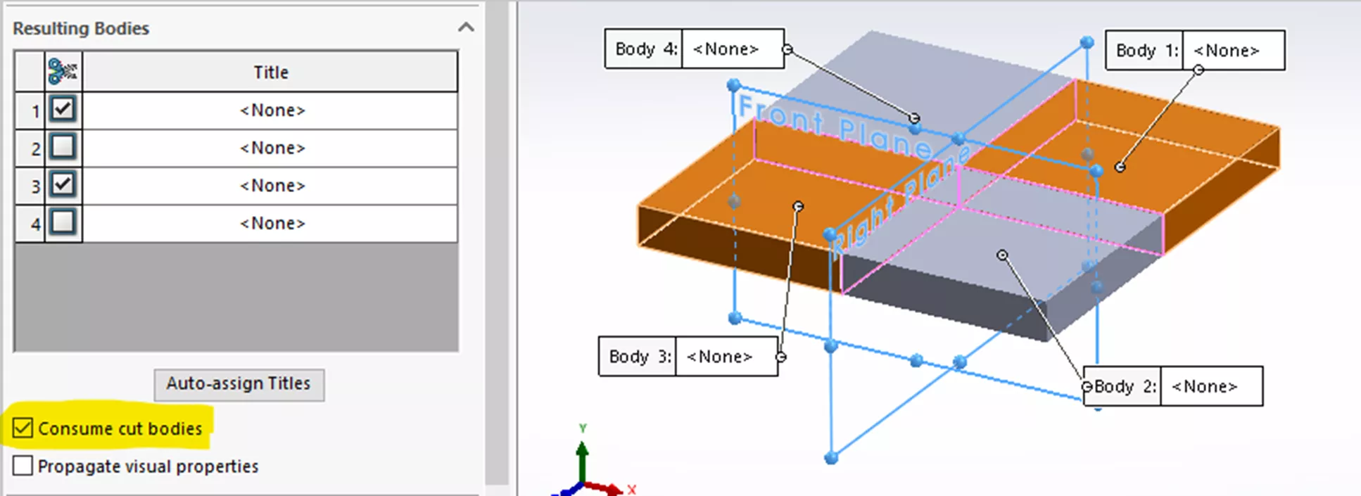
Resulting Bodies
Lastly are the Resulting Bodies.
One or more check boxes are checked to define the split body to keep (or delete if Consume cut bodies is checked). At least one Resulting Bodies box must be checked to create the split.
There is often the misconception that not checking the box will delete the solid body. This is not true. The bodies from the unchecked boxes stay fused together as one body (if possible).
Let’s look at the examples below. These are all the same geometry with different check selections.
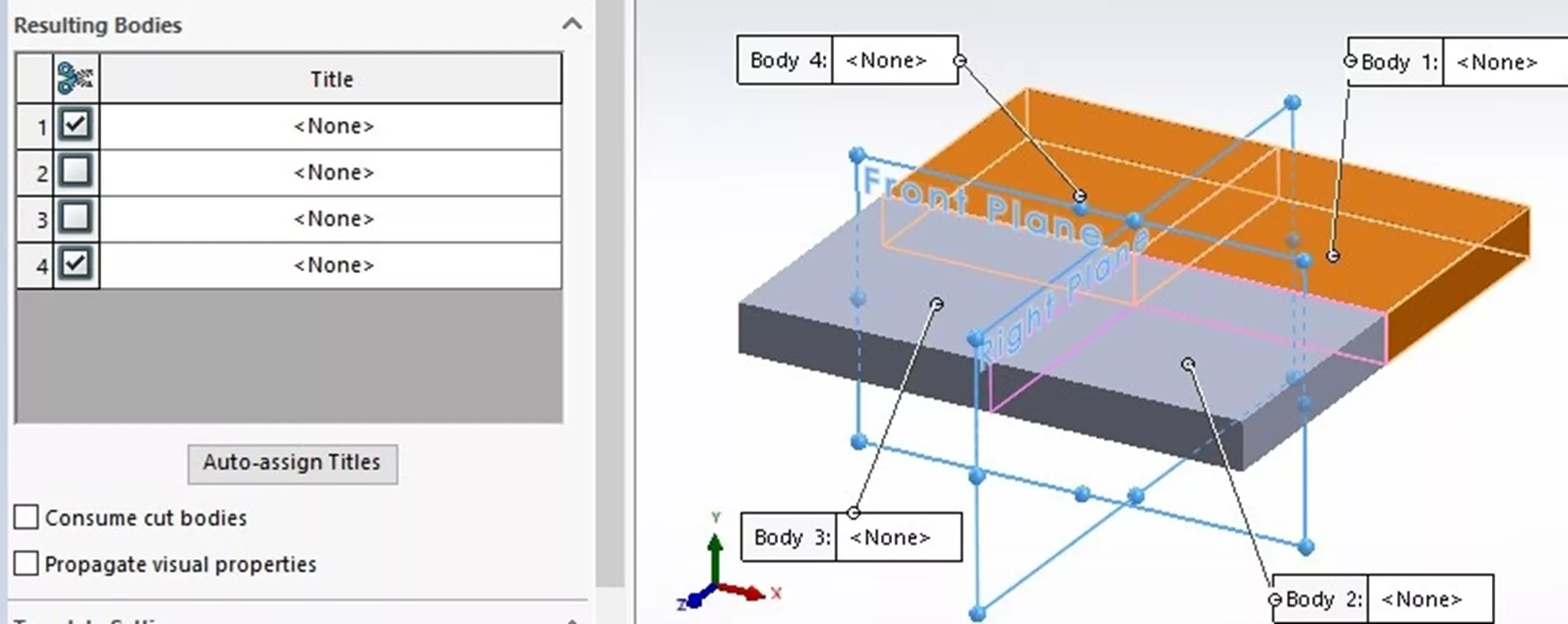
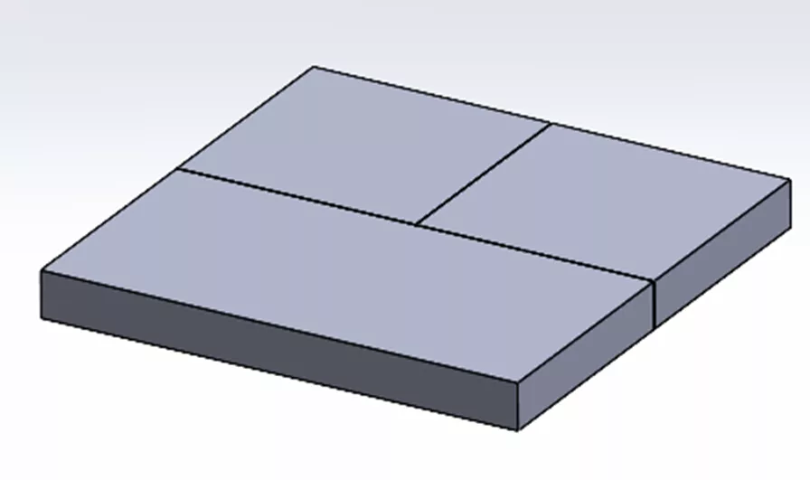
Example 1
Here, the first box is checked under Resulting Bodies. (The checked geometry highlights orange.)
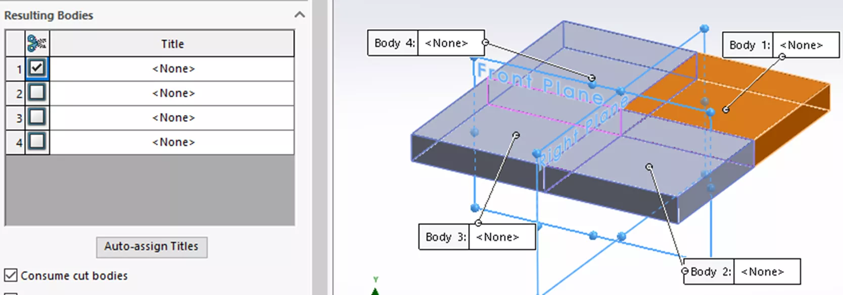
The three unchecked bodies stay fused. This results in two bodies.
Example 2
Here, the first and last boxes are checked under Resulting Bodies.
This results in three bodies.
Example 3
In this example, the first and third boxes are checked under Resulting Bodies.
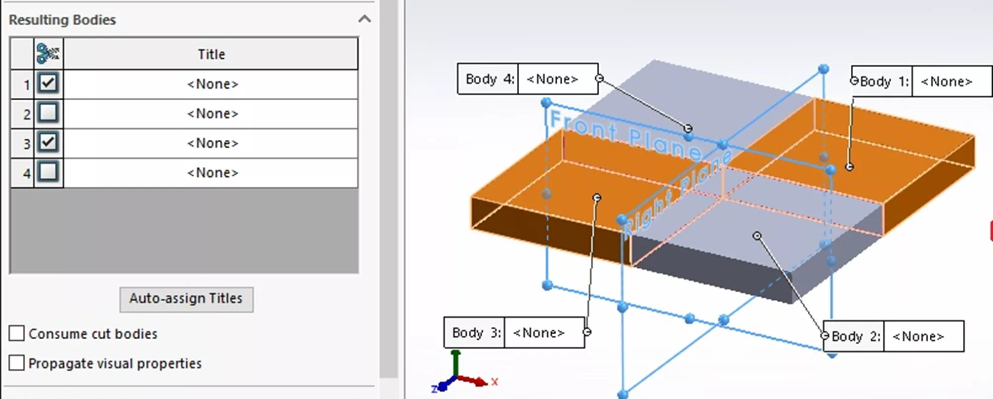
This results in four bodies.
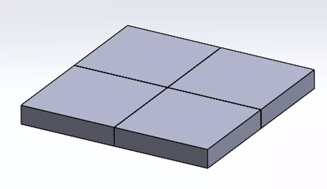
Why are four bodies created in this instance? This is because the two unchecked bodies are only touching at their corners after being split. Solids cannot merge at a contact edge.
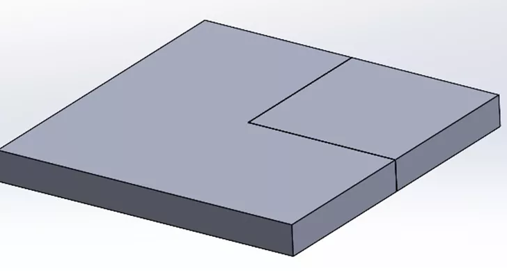
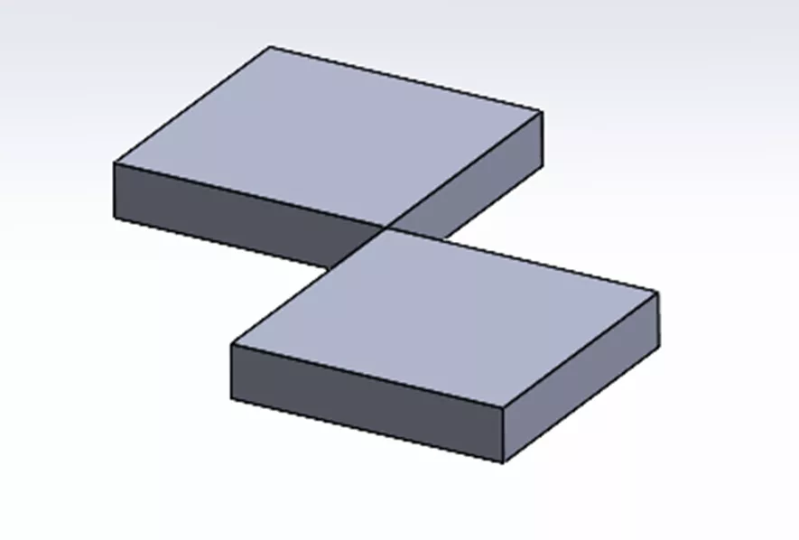
Example 4 Using Consume Cut Bodies
Here, as with Example 3, the first and third boxes are checked under Resulting bodies. In addition, the Consume cut bodies box is also checked. This results in the two checked bodies being deleted.
The resultant split:
Auto-assign Titles
In the previous examples, no Titles (or Names prior to 2023) were assigned. Titles are simply the file name for the externally saved part(s). If no Titles are assigned, the software leaves the resulting bodies internal to the part file. No external files are created.
If Titles are assigned by either clicking the Auto-assign Titles button or by double-clicking a field, then both internal bodies and external part(s) files are saved. The external file stays linked to the generating part(s) file by default. Changes made to the generating file before the Split feature will be pushed out to the part(s). Changes after the Split feature will not. The exported parts can be modified independently of the generating part.