• This forum is the machine-generated translation of www.cad3d.it/forum1 - the Italian design community. Several terms are not translated correctly.

Spaceclaim 2011 (r7)

  • Thread starter Thread starter Matteo
  • Start date Start date
hi matteo, a small note that is classic for video-demo.
It is easy to work on an export stl, problems arise with scan stl in which you do not have precise references and often details to scan are deformed (almost always in the abs loaded for the engine compartment).
How do you do this to avoid madness? (taking measures on a piece board is suicide) :-)
hi, the demo is not mine (it is from de), in fact I do not like demos where "everything is always good" (there are those who make demos with powerpoint ...) in fact when a customer asks me information about sc I answer that the best thing is to apply the software to a concrete case.

in these cases there are various approaches to follow: if the destination is a model for the calculation fem or I only refer to the points of the championship model building me a reasonably precise geometry, or I use one of the many spaceclaim plugins (in this case in common with rhino) dedicated to the calculation fem starting from stl "difficile" geometry (e.g. scano&solve). if instead I need a very detailed "smooth" geometry there are plugins that are based on the interpolation of a cloud of points to build a surface (e.g. sycode for spaceclaim). in summary (no problem to specify it): in complex cases the basic license is not enough, but there are possibilities for expansion.
I'll throw it there.
a spline guide?
I don't understand. If you have any examples to attach, I'll think about it.

Bye!
 
I'll throw it there.
a spline guide?
you have to have functions of manipulation of the stl able to report the data to the desired conditions.
conceptually they are similar to warp functions (deformation) and can follow different criteria.
 
you have to have functions of manipulation of the stl able to report the data to the desired conditions.
conceptually they are similar to warp functions (deformation) and can follow different criteria.
I think it's me. It's not my industry. But if you want to go deeper and have a simple example (but not trivial like that demo) we can see together what can do sc.
 
I'll give you a simple example.
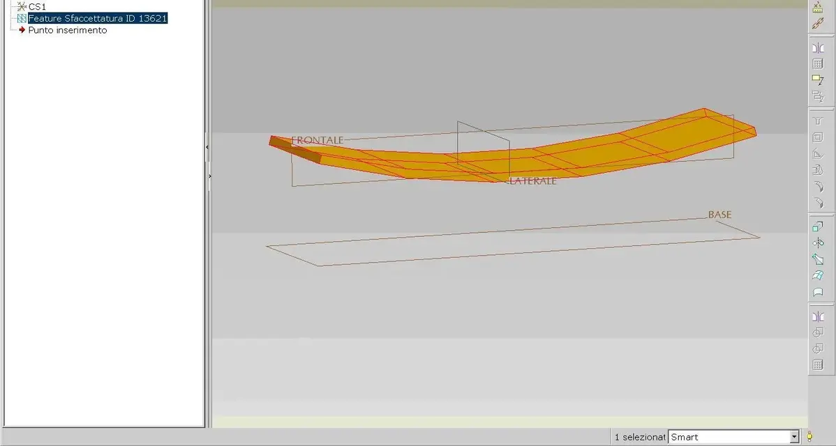
in image 1 the sl imported from scanning with deformation problems.
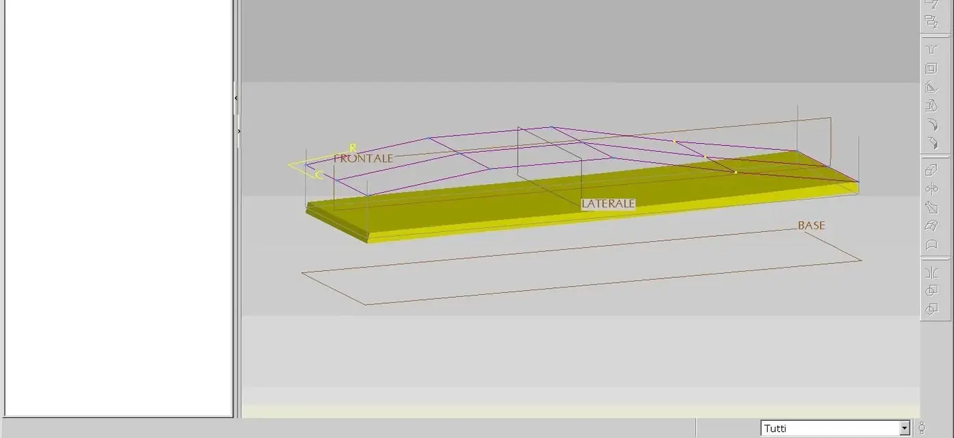
in image 2 the "raddrized" stl to allow a reconstruction of the correct geometry.
in practice manipulating the poles you can see in image 2 (there are different modes of manipulation) you correlate the data deformations.
this, in certain areas, is a very important function.
you have to think of the sl as a simple measurement of the piece.
if the piece is deformed it is practically impossible to reconstruct the geometry following the sl and makes the same unusable.
in this case you are forced to measure the piece manually.
 

Attachments

  • 1.webp
    1.webp
    32.5 KB · Views: 15
  • 2.webp
    2.webp
    28.9 KB · Views: 14
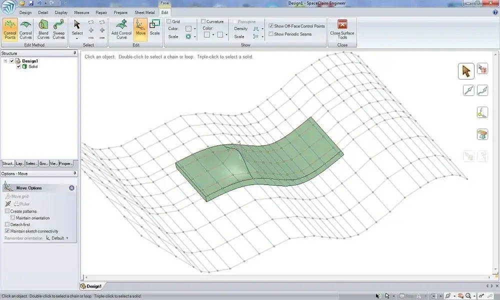
You mean something like that?
Yes, if the function is applicable to stl you are in place below this point of view.
you just have to be careful how to use it because this function if applied does not properly deform the thicknesses and limit curves.
 
Yes, if the function is applicable to stl you are in place below this point of view.
you just have to be careful how to use it because this function if applied does not properly deform the thicknesses and limit curves.
Yes, the same drawback I found.
for what concerns the stl: wanting I can also move the individual knots (not with this function, with the normal "move" command.

Bye!
ps: it sounds weird when you write "you're" in place... Maybe "fossimo"! I for sc are only a consultant (being an experienced user closes customers before resale and after). I wouldn't be sorry to make direct resale, but for now... Let us say that there is no room now;)
 
Yes, but the original size was high.
we are talking about details that have undergone deformations for bad molding or rites inherent in the molding itself.
quoting and adding that any geometry obtained by sampling is eventually an interpolation of the original.
 
Yes, but the original size was high.
we are talking about details that have undergone deformations for bad molding or rites inherent in the molding itself.
but certainly I don't think if you change it according to what comes to you by touching points you get to the result.
If you talk about warp I think plastic retreats and twists come into play due to plastic injection.
and I don't think if I deform it as best I find the result that I get is the right one.
but I should deform it on the contrary, so the result must be the exact opposite of the one proposed by the scan.
quoting and adding that any geometry obtained by sampling is eventually an interpolation of the original.
there is no doubt but the distance from the original piece (matized) to the deformed one ( stl ) must be repeated otherwise after the printed one you get the result equal to the scan.
 
but certainly I don't think if you change it according to what comes to you by touching points you get to the result.
If you talk about warp I think plastic retreats and twists come into play due to plastic injection.
and I don't think if I deform it as best I find the result that I get is the right one.
but I should deform it on the contrary, so the result must be the exact opposite of the one proposed by the scan.
in fact the right result you get it with modeling, and here it takes the eye and care of those who know the job.
the molder does not pass the deformed.
you just need to have a base for a proper modeling.
Otherwise what would be the alternative solution?
there is no doubt but the distance from the original piece (matized) to the deformed one ( stl ) must be repeated otherwise after the printed one you get the result equal to the scan.
I don't understand that.
the result of the modeling should not be equal to the scanning... you must follow the design intent, otherwise you pull out an abortion.
 
I'm just saying this.

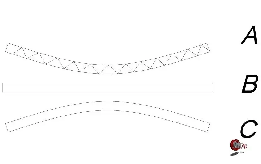
if at the stl file we have and want to get the b we have to model it in c

because otherwise if we model like b at the end of the print we get again
 

Attachments

  • IMMAGE.webp
    IMMAGE.webp
    13.1 KB · Views: 2
I'm just saying this.

if at the stl file we have and want to get the b we have to model it in c

because otherwise if we model like b at the end of the print we get again
Now I know what you mean.
Usually these problems arise from a mold design error or molding mode (not geometry itself).
However within certain limits the deformations are considered acceptable, because they are compensated in the assembly phase.
for which the practice is to model the piece on the floor and then limit them to the minimum with a correct design of the mold and the molding process itself.
 
I'm sorry, but if you first left yourself saying you have to be careful about warp now you don't need it?
 
I think the discussion took a turn.

x flavio: I remember that in another discussion you had the opportunity to talk to us about the ability of omnicad to manage the elastic return of the material or the recoveries of foundry (I remember that he had amazed me in positive).

clearly spaceclaim does not handle this type of problems, being thought for a different use (I would say very horizontal, while omnicad is extremely vertical and specialized).
the same proe brought as example by maxopus (I have used it for years and I confirm that it is very powerful in the "reverse" sector is less specialized but more versatile than omnicad: clear that in certain niche applications it can compete. I would therefore say that it makes no sense to continue on this road, even because if we want to talk about what proe and sc do and that omicad does not suffice 100 pages of forums.
 
I'm sorry, but if you first left yourself saying you have to be careful about warp now you don't need it?
I don't understand where you want to go, it's clear that warp can cause variations in the thicknesses (although pro/e has a function that can control them).
This does not mean that you have to model the deformed piece on the contrary.
How do you make sure you screw him up and come up straight?
Think that by applying a symmetrically opposite deformation you can get the straight piece? it would be easy, the thing is much more complex.
then if a plastic casing comes out of the boarded mold of 2-3 mm what do you want it to rub at all if they have no problems in the assembly phase?
I repeat, it is deformations considered by all admissible.
 

Forum statistics

Threads
44,997
Messages
339,767
Members
4
Latest member
ibt

Members online

No members online now.
Back
Top