xxi
Guest
You have to apologize I made a gaffe, I can't read!!!! ahahah.. thanks always mechanicm that helps me even in the banality. . .
my drawing prof said that it is "the dog who bites the tail"... try to make a course of constructions of machines or elements without knowing how to read an overall. I see it hard. try to correctly quote a particular with relative tolerances without knowing the technology and cycles of processing. I see her even harder. I remember that the design prof dedicated a couple of hours to explain how the lathe and the milling machine worked to make us understand a bit the "functional" quota speech. It is clear that it is not enough 2 hours to learn how to quote.It's a half done job, I know. In fact, I don't understand why you don't do more "suitable" exercises or why you don't put your drawing courses after the design courses. . or because you do not begin to explain something in the drawing courses perhaps because you assume a pre-arranged tacnic institution requirement.
Yes, more or less and depends how. must be changed the wheel because as it is wrong and incorrect.http://dismac.isten.ing.unipg.it/common_files/disegno/_13_ruotedentate.pdfIs it okay with the right teeth wheel on page 7?
")
I'll look at you tonight and I'll tell you tomorrow:I write in this topic because this week's problem is always a reducer, always for the same design course of topic initiator machines.
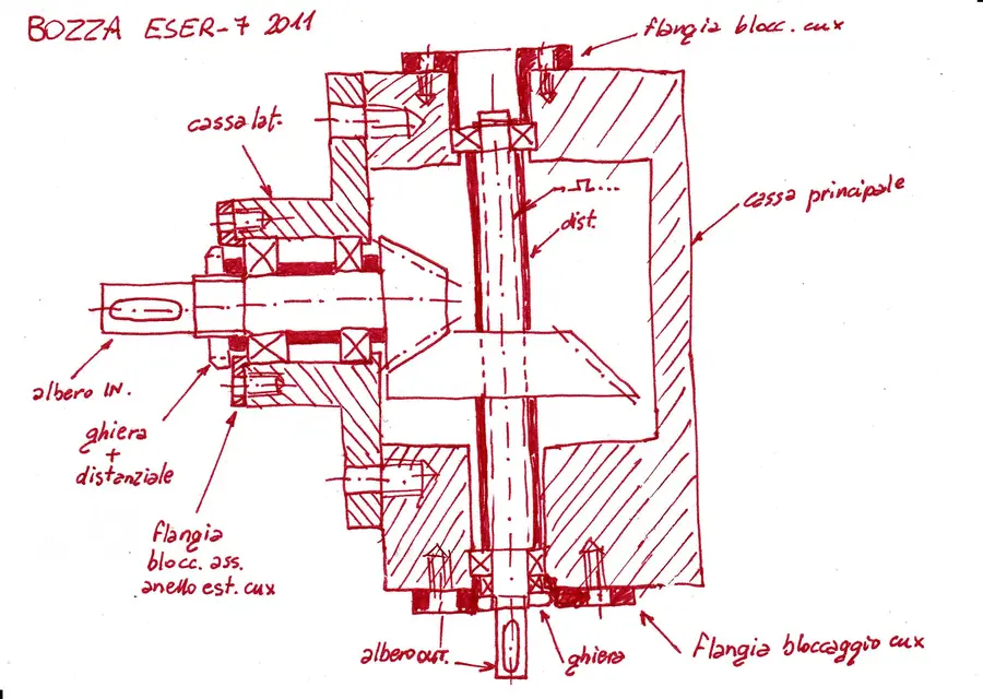
http://dmmf.mec.uniroma2.it/docs/dm1_2011/eser-7_2011.pdfon the input shaft I had foreseen two oblique ball bearings arranged precisely to x. on the exit shaft, since the presence of a double-acting brace is required, I predicted the use of two additional radial bearings. if I do not err these last must be a locked both in place and on the tree, one stuck only on the tree and with game in place. I then calculated with the appropriate formulas the rays, the angles of primitive cone etc.. for the wheels... There are no calculations required for efforts and stresses. then the module and everything is chosen arbitrarily.
I have great doubts as to the area where you go to place the piece pinnacle of the input shaft. there are those who say that it must be a special case that must be sampled, being it a real box, not like the rest of the body of the reducer that instead should not be sampled, but drawn normally since the reducer is actually divided in that way into two pieces. How should this case be placed? how do I enclose the pinion while also considering the other wheel?
second big question... how can I keep the scanned coupling in place? Are they good spacers on both sides?
Last thing, can I use a spacer to keep the oblique input shaft bearings away from each other? placing this spacer on the horse of a part of tree with marginal narrowing of diameter of the tree (obviously realized avoiding double lines of the spacer itself and having the diameter of the two parts on the right and left larger)? theoretically it does not compromise the assembly.
Thank you very much for your patience and for sure stupid questions
Here we are... then we have:I write in this topic because this week's problem is always a reducer, always for the same design course of topic initiator machines.
http://dmmf.mec.uniroma2.it/docs/dm1_2011/eser-7_2011.pdf
Please:wink: Then I come to answer:Thank you so much for your always precious help and especially the time you spent for your sketch. Thank you very much. Now I'll put my version in the morning.
I leave you two questions:
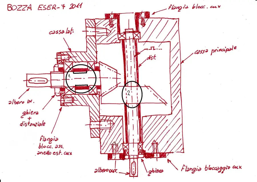
because in zone 1 often in the examples the book makes a reduction in the diameter of the tree under the spacer (without getting to the extremes) as I misdesigned you with paint?
surely the answer to this question is seen that the sketch was made by an expert designer like you, but the groove on the tree is possible to do it even on a stretch with a uniform diameter? in the sense is it not necessary that the groove on the tree begin where there is a change of diameter? can also start and finish on a stretch with the same diameter? I apologize for the scrumptical question, but on the book all examples of grooves are made at the beginning of a change of diameter... .
Thank you very much again! ! !
I have annexed the areas concerning my questions
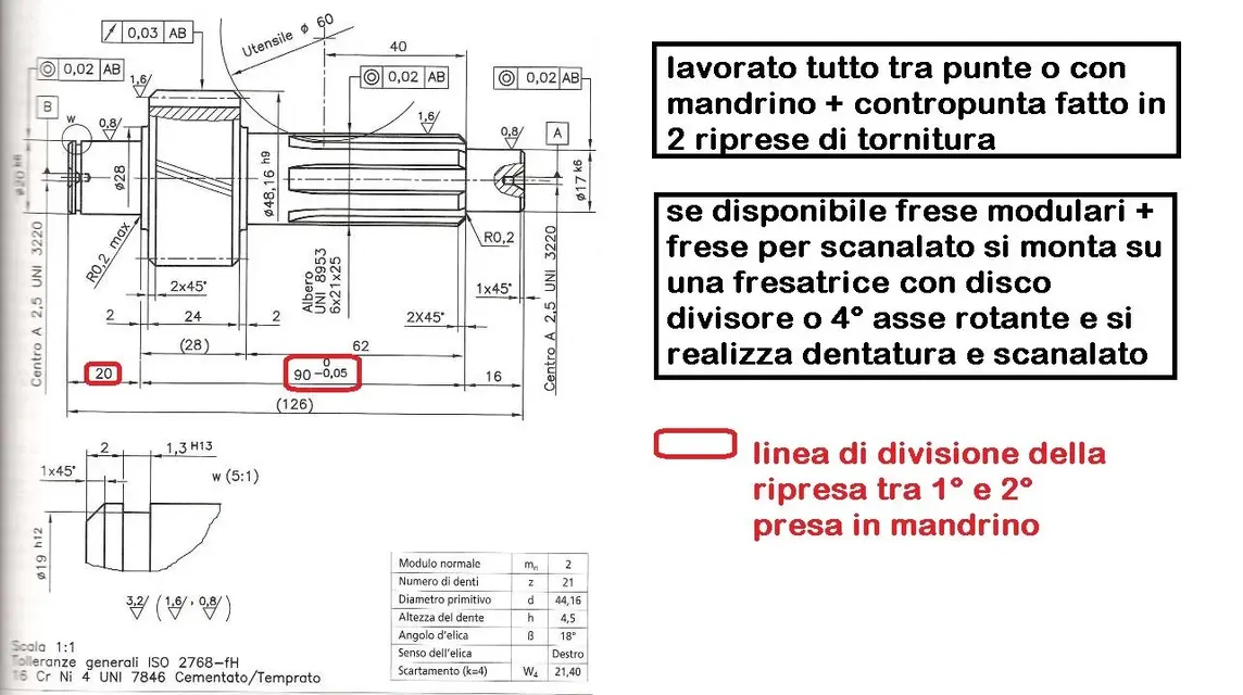
how much I love these 40 lines or more to have to read 20 times because I lose the thread of the speech. Wasn't posting a drawing easier?with regard to the second part of the exercise, that concerning geometric and dimensional tolerances with relative quotation only of the input shaft.. It's okay if I act like this:
1) for dimensional tolerances pongo on the seat of the two oblique bearings a dimensional tolerance j5 (loads and average speed). I also put on the quarry for tongue a special tolerance
2) with regard to quotations this time I have to write (as in the previous exercise) those both functional (in series) and technological/working (looking at "scale), or are the latter not explicit?
3) with regard to the piece sprocket is right if I affix the quotation table of the conical wheel, even if it is a piece sprocket?
4) regarding roughness is it right to put on the pinion a 2.5 in the external part of the teeth and 1.2 on the internal cavities of the teeth? Is there any roughness on the bearings?
5) regarding the second oblique bearing that touches me on the shouldering I have often seen the professor tend to put a thin line "similgolaf"... Is it really enough that the shoulder connection radius is less than the bearing connection radius?
6)as regards the geometric tolerances pongo as a plane out of the tree axis on the shoulder exactly before the pinion, then placing on the tooth an oscillation toll of 0.05.
Is it necessary that I then define another plane b from the other head of the tree and then put a total oscillation on the bearing seats? and if you like to indicate the tolerance of oscillation on your teeth instead of as mentioned before? Thank you so much for your patience!
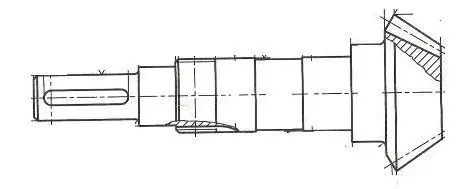
- I'd say there's already a quota. substantially quoted so does not make sense. then for so long we put zero in the head and we put all quotas second axis x without having to ask the problem, all tolerances will be referred to uni en iso 2768-x but then if something is not found there is not to complain.thank you very much for your precious mechanical helpmg, I put you the last (spero) question. for the arrangement of the quotas on the tree is fine this sketch (I do not see any other dimensional tolerances to put beyond the j5 of the bearing seats and the p9 of the hollow tab):
http://nobody32.interfree.it/p10.jpglack geometric oscillation tolerances that you have to tell me if they're okay like this:
1) reference axes to where there is the quarry tongue and b on the left shoulder of the pinion
2) total oscillation on the two bearing seats (of course a-b)
3) partial oscillation of the tooth of the pinion with respect to the only plane b.
for roughness I thought instead 0.8 on the two bearing seats (on the one with the throat f also on the rectification wall), 1.6 on the outside tooth, 0.8 on the inside tooth.
Thank you so much again and sorry to bother you!
ball bearings hold both radial and axial loads.Mechanicalmg make me understand better.. Ball bearings hold only radial loads, only axial rods; ball bearings, double crown, tapered rollers bear both radial and axial loads for the alpha angle?
It's like mbt said. However, radial ball bearings or roller bearings are usually used for predominantly radial loads, axles for thrusts mainly in the direction of the axle and angled ones such as conical roller bearings for heavy loads in axial/radial direction.Mechanicalmg make me understand better.. Ball bearings hold only radial loads, only axial rods; ball bearings, double crown, tapered rollers bear both radial and axial loads for the alpha angle?