• This forum is the machine-generated translation of www.cad3d.it/forum1 - the Italian design community. Several terms are not translated correctly.

catia v5 - surface modeling

  • Thread starter Thread starter Tony Designer
  • Start date Start date

Tony Designer

Guest
Good morning to all, I'm sorry I need information for those who knew caia at an advanced level.
I created the body of a simple kitchen faucet with the shape design module, consisting of 2 semi-archies, 1 floor prioettato at distance of 83 mm. and 4 closing lines in coincidence with the 2 semi-archies.
so much to understand the result that I wanted to get is the body of a simple tap cut in half.
after joining the 4 lines with the 2 semi-archies, I created the 4 fillings, then the base surface which is rectangular trapezoidal, the 2 semi-archies and the upper closing surface.
I created the union and then closing surface.
the problem and that I would like to turn the tube into a solid.
I went to the part-design module and tried to make a test pocket, but nothing happens.
Can you tell me what the mistake is?
Thank you.
 
I can assume that until the point you created the union went all right, then you have to switch to the part design module and use the command closes a surface
(I assume that instead you in shape design after the union closed a surface with volume (violet icon) and then you went to part design)

Let me know.

Hi.
hi gianni, yes excuse me from the form generative shape design I joined with the blue icon (not purple) and passed to the module part-design and closed the surfaces.
the problem and when I use the pocket tool, the operation is performed but the geometry is not subtracted.
I don't understand why the color of my geometry remains yellow in the par design module.
If it was a solid, wouldn't it have to take the gray color?? probably after joining the parts and closing the surfaces is missing some alleged operation.
 
If in part design you used "close a surface", the operation is done in the partbody and you can see it in the tree and in the 3d (grey), if you still see the yellow geometry, I think it is simply because the surface you have closed is still visible, just hide it.

Let me know.

Hi.
 
If in part design you used "close a surface", the operation is done in the partbody and you can see it in the tree and in the 3d (grey), if you still see the yellow geometry, I think it is simply because the surface you have closed is still visible, just hide it.

Let me know.

Hi.
Thanks gianni ok! well, from the part design I found that from the union command (show/hide) I can view the gray and yellow colors of the geometry.
therefore setting the gray color, I managed to carry out the pocket command as test exercise and this time it works.
It is very interesting to create a simple part of surface and turn it into solid.
I managed to complete the solid body tap in part design together with 3 other elements and then joined in the assembly design module.
all right thanks gianni:smile:
 
Good morning
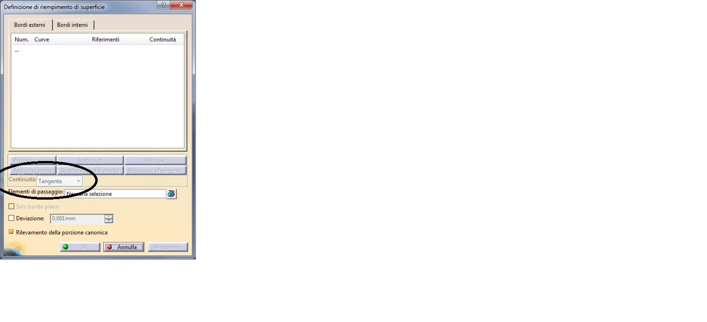
Does anyone know how to change "tangence"?
I attach the image,the operation is "filling" is use catia r25.
thanks in advanceImmagine.webp
 
If I'm not mistaken, you should first begin to select the edges or curves on which the surface will pass, then select the surfaces in which to maintain the continuity (contact, tangency or curvature), then, then, then, go tendon, which at that point should be active, and then select between the available options.
 

Forum statistics

Threads
44,997
Messages
339,767
Members
4
Latest member
ibt

Members online

No members online now.
Back
Top